If you ever looked at the wireshark capture of EIGRP or RIP packets you might have seen that the TTL (Time to Live) value is 2. You would probably expect to see a TTL of 1 here since these multicast packets aren’t routed between subnets. In this tutorial I’ll show you why these packets have a TTL of 2.
To demonstrate this I will use the following frame-relay hub and spoke topology:

We have one hub router and two spoke routers. First I’ll configure frame-relay using the physical interfaces and a single subnet:
Hub(config)#interface serial 0/0
Hub(config-if)#encapsulation frame-relay
Hub(config-if)#ip address 192.168.123.1 255.255.255.0
Hub(config-if)#no shutdownSpoke1(config)#interface serial 0/0
Spoke1(config-if)#encapsulation frame-relay
Spoke1(config-if)#ip address 192.168.123.2 255.255.255.0
Spoke1(config-if)#no shutdownSpoke2(config)#interface serial 0/0
Spoke2(config-if)#encapsulation frame-relay
Spoke2(config-if)#ip address 192.168.123.3 255.255.255.0
Spoke2(config-if)#no shutdown
We’ll configure EIGRP on all routers:
Hub, Spoke1 & Spoke2:
(config)#router eigrp 123
(config-router)#network 192.168.123.0
We now have a neighbor adjacency between Hub/Spoke1 and Hub/Spoke2. Let’s take a look at an EIGRP capture in wireshark to see what the TTL looks like:
As you can see the TTL is 2 but why? A TTL of 1 would be enough since these packets aren’t routed between subnets. The answer to this question is that we need it for communication between spoke routers.
To demonstrate this we will configure spoke1 and spoke2 to become EIGRP routers and take a look at the wireshark capture again. Before the spoke routers can become neighbors they’ll require a frame-relay mapping:
Spoke1(config)#interface serial 0/0
Spoke1(config-if)#frame-relay map ip 192.168.123.3 201Spoke2(config)#interface serial 0/0
Spoke2(config-if)#frame-relay map ip 192.168.123.2 301
Spoke1 and spoke2 are now able to reach each other. We will use the EIGRP neighbor command to make sure all routers become neighbors with each other:
Hub(config)#router eigrp 123
Hub(config-router)#neighbor 192.168.123.2 serial 0/0
Hub(config-router)#neighbor 192.168.123.3 serial 0/0Spoke1(config)#router eigrp 123
Spoke1(config-router)#neighbor 192.168.123.1 serial 0/0
Spoke1(config-router)#neighbor 192.168.123.3 serial 0/0Spoke2(config)#router eigrp 123
Spoke2(config-router)#neighbor 192.168.123.1 serial 0/0
Spoke2(config-router)#neighbor 192.168.123.2 serial 0/0
As you can see the spoke routers have become neighbors:
Spoke1#
%DUAL-5-NBRCHANGE: IP-EIGRP(0) 123: Neighbor 192.168.123.1 (Serial0/0) is up: new adjacency
Spoke2#
%DUAL-5-NBRCHANGE: IP-EIGRP(0) 123: Neighbor 192.168.123.2 (Serial0/0) is up: new adjacency
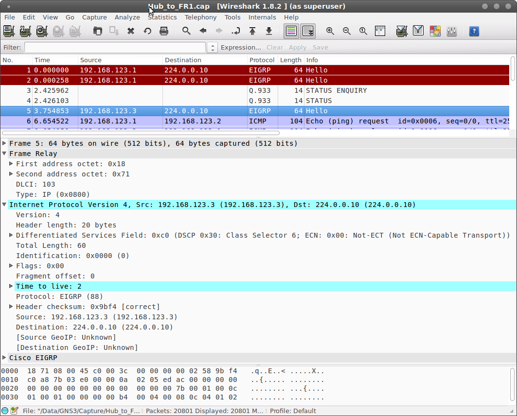
Let’s get back to wireshark and look at an EIGRP packet from spoke1 to spoke2. The first capture is an hello packet that the Hub receives from spoke1:

As you can see this IP packet is sent from spoke1 to spoke2 and it has been received on DLCI 102 on the hub router, it has a TTL of 2. This packet will be forwarded by the hub router to spoke2 and it will look like this:

This capture shows the same IP packet from spoke1 to spoke2 but it’s sent by the hub router on DLCI 103. As you can see the TTL has been decreased and has a value of 1. If spoke1 would have created a packet with TTL 1 then the hub wouldn’t be able to forward it towards spoke2.
Hopefully this tutorial has helped you to understand the reason behind using a TTL value of 2. If you have any questions please leave a comment!
No comments:
Post a Comment