In this lesson I want to show you a basic configuration of OER (Optimized Edge Routing). If you have no idea what OER is or why you want to use this, take a look at my
introduction to OER first.
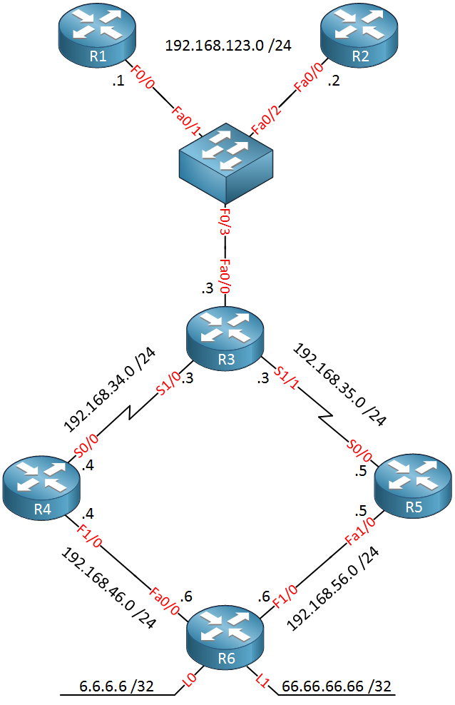
OER is not a simple topic and the configuration can become quite complex because of all the policies. In this example i’m going to walk you through a simple scenario where we configure an MC (Master Controller) and BR (Border Router). Let me show you the topology:
There are quite some routers so let me explain this topology to you:
- R1,R2 and R3 belong together, the serial links on R3 are the “edge” of our network.
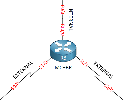
- R3 will be configured as the master controller but also as a border router. You can configure both on the same router.
- R3 has two serial links that we will use as “WAN” links. The serial 1/1 interface has a bandwidth of 64 kbps and the serial 1/0 interface has a bandwidth of 1024 kbps.
- R1 and R2 will be used as “traffic generators”.
- R1 will have a TCP connection to the loopback0 interface of R6.
- R2 will send ICMP traffic to the loopback1 interface of R6.
- R4 and R5 are nothing special, they are only used as endpoint for the serial links.
- R6 is only used as an endpoint for our “traffic generators” R1 and R2.
By default I will send all traffic over the slow 64 kbps link using a static route, we will use a floating static route to use the 1024 kbps link as a backup. The goal of this lab example is to configure OER to automatically switch traffic flows from the slow 64 kbps link to the 1024 kbps link. Sounds like fun right?
Let’s get to the configuration part!
To keep things simple I will use static routes for connectivity:
R1(config)#ip route 0.0.0.0 0.0.0.0 192.168.123.3
R2(config)#ip route 0.0.0.0 0.0.0.0 192.168.123.3
R1 and R2 will use a static route pointing to R3.
R3(config)#ip route 0.0.0.0 0.0.0.0 192.168.35.5
R3(config)#ip route 0.0.0.0 0.0.0.0 192.168.34.4 5
R3 has two default routes. The first one points to R5 and this is the static route that we will find in the routing table. The second static route is our floating static route pointing to R4. It has an administrative distance of 5.
Something that you should remember about OER is that it requires a “parent route” in order to use a certain link. If I didn’t configure the static route pointing to R4 than OER will never be able to use the serial 1/0 interface!
R4(config)#ip route 192.168.123.0 255.255.255.0 192.168.34.3
R4(config)#ip route 6.6.6.0 255.255.255.0 192.168.46.6
R4(config)#ip route 66.66.66.0 255.255.255.0 192.168.46.6
R5(config)#ip route 192.168.123.0 255.255.255.0 192.168.35.3
R5(config)#ip route 6.6.6.0 255.255.255.0 192.168.56.6
R5(config)#ip route 66.66.66.0 255.255.255.0 192.168.56.6
On R4 and R5 we will configure static routes so they can reach the 192.168.123.0 /24 network and the loopback interfaces of R6.
R6(config)#ip route 0.0.0.0 0.0.0.0 192.168.46.4
R6(config)#ip route 0.0.0.0 0.0.0.0 192.168.56.5
On R6 we’ll configure two default routes pointing towards R4 and R5. I don’t care which path R6 will use…
Let’s check if R1 and R2 can reach R6:
R1#ping 6.6.6.6

Type escape sequence to abort.
Sending 5, 100-byte ICMP Echos to 6.6.6.6, timeout is 2 seconds:
!!!!!
Success rate is 100 percent (5/5), round-trip min/avg/max = 8/11/12 ms

R1#ping 66.66.66.66

Type escape sequence to abort.
Sending 5, 100-byte ICMP Echos to 66.66.66.66, timeout is 2 seconds:
!!!!!
Success rate is 100 percent (5/5), round-trip min/avg/max = 8/16/32 ms
R2#ping 6.6.6.6

Type escape sequence to abort.
Sending 5, 100-byte ICMP Echos to 6.6.6.6, timeout is 2 seconds:
!!!!!
Success rate is 100 percent (5/5), round-trip min/avg/max = 8/11/12 ms

R2#ping 66.66.66.66

Type escape sequence to abort.
Sending 5, 100-byte ICMP Echos to 66.66.66.66, timeout is 2 seconds:
!!!!!
Success rate is 100 percent (5/5), round-trip min/avg/max = 8/16/32 ms
R1 and R2 can reach R6 so my static routes are working. Let’s check the path that they are currently using:
R1#traceroute 6.6.6.6

Type escape sequence to abort.
Tracing the route to 6.6.6.6

1 192.168.123.3 4 msec 4 msec 4 msec
2 192.168.35.5 8 msec 8 msec 8 msec
3 192.168.56.6 8 msec *  8 msec
We are using the path from R3 to R5, this is because of the default route that I configured on R3:
R3#show ip route static
S*   0.0.0.0/0 [1/0] via 192.168.35.5
So far so good, connectivity is working. Before I start with the configuration of OER I want to change the bandwidth of the serial interfaces on R3:
R3(config)#interface serial 1/1
R3(config-if)#bandwidth 64
R3(config-if)#exit
R3(config)#interface serial 1/0
R3(config-if)#bandwidth 1024
R3(config-if)#exit
R3#show interfaces serial 1/1 | include BW
MTU 1500 bytes, BW 64 Kbit, DLY 20000 usec,
R3#show interfaces serial 1/0 | include BW
MTU 1500 bytes, BW 1024 Kbit, DLY 20000 usec,
R3 now thinks that serial 1/1 is 64kbit and serial 1/0 is 1024 kbit. Of course this doesn’t change the actual bandwidth but OER will believe that this is the bandwidth of the interfaces. Now let’s take a look at OER!
When we configure OER we have to configure the master controller and the border router(s). OER needs to know what the internal and external interfaces are. R3 will be both a border router and the master controller. The FastEthernet 0/0 interface is internal and the two serial links are external. OER requires authentication and it has to be done with a key chain just like EIGRP. Here’s what the configuration looks like:
R3(config)#key chain OER
R3(config-keychain)#key 1
R3(config-keychain-key)#key-string NETWORKLESSONS
I’ll keep it simple, the key chain is called “OER” and the password will be “NETWORKLESSONS”. Now let’s configure the master controller role:
R3(config)#oer master
R3(config-oer-mc)#border 192.168.123.3 key-chain OER
R3(config-oer-mc-br)#interface fastethernet 0/0 internal
R3(config-oer-mc-br)#interface serial1/1 external
R3(config-oer-mc-br-if)#exit
R3(config-oer-mc-br)#interface serial1/0 external
R3(config-oer-mc-br-if)#exit
R3(config-oer-mc-br)#exit
R3(config-oer-mc)#exit
First I use the oer master command to enable the MC role. Next step is to configure the border router and specify the key-chain. In my example I’m using IP address 192.168.123.3 but on a production network it’s better to use loopback interfaces to establish the neighbor adjacency between the master controller and border router(s). OER uses a TCP connection in case you were wondering.
I also configured the interfaces and specified whether they are internal or external, this is something you have to do for all border routers in the network! Now let’s configure the border router role:
R3(config)#oer border
R3(config-oer-br)#local fastEthernet 0/0
R3(config-oer-br)#master 192.168.123.3 key-chain OER
Use the oer border command to get into the border router configuration. The local command specifies the interface that will be used to source the TCP connection from. Last but not least we configure the master controller and the key chain. Now before we continue it’s a good idea to check if the border router has successfully connected to the master controller:
R3#show oer border
OER BR 192.168.123.3 ACTIVE, MC 192.168.123.3 UP/DOWN: UP 00:01:24,
Auth Failures: 0
Conn Status: SUCCESS, PORT: 3949
Exits
Fa0/0 INTERNAL
Se1/0 EXTERNAL
Se1/1 EXTERNAL
Use show oer border to verify your configuration. We can see that it has successfully connected to the master controller and we can see that it uses TCP port 3949. We also see the internal and external interfaces.
We can also take a look at the master controller part, here’s how to do it:
R3#show oer master
OER state: ENABLED and ACTIVE
  Conn Status: SUCCESS, PORT: 3949
  Number of Border routers: 1
  Number of Exits: 2
  Number of monitored prefixes: 0 (max 5000)
  Max prefixes: total 5000 learn 2500
  Prefix count: total 0, learn 0, cfg 0

Border           Status   UP/DOWN             AuthFail
192.168.123.3    ACTIVE   UP       00:03:31          0

Global Settings:
  max-range-utilization percent 20
  mode route metric bgp local-pref 5000
  mode route metric static tag 5000
  trace probe delay 1000
  no logging

Default Policy Settings:
  backoff 300 3000 300
  delay relative 50
  holddown 300
  periodic 0
  mode route observe
  mode monitor both
  mode select-exit good
  loss relative 10
  unreachable relative 50
  resolve delay priority 11 variance 20
  resolve utilization priority 12 variance 20

Learn Settings:
  current state : DISABLED
  time remaining in current state : 0 seconds
  no throughput
  no delay
  no protocol
  monitor-period 5
  periodic-interval 120
  aggregation-type prefix-length 24
  prefixes 100
  expire after time 720
Use show oer master to see information from the MC’s role. We see that the master controller is running, we have a border router and two exit paths for our network. It also shows us the default policy. Explaining the policy settings it outside the scope of this lesson as there’s quite some stuff we can do. I will cover it later in another lesson.
Before I start traffic generation on R1 and R2 I will enable logging on the master controller. This wil output everything on the console, it’s just like a debug and it will show us what OER is doing:
R3(config)#oer master
R3(config-oer-mc)#logging
Now let’s generate some traffic from R1 and R2, here’s what I will do:
- R1 will connect to IP address 6.6.6.6 using TCP.
- R2 will send ICMP traffic to 66.66.66.66.
R6(config)#service tcp-small-servers
R1#telnet 6.6.6.6 19
Trying 6.6.6.6, 19 ... Open
 !"#$%&'()*+,-./0123456789:;<=>?@ABCDEFGHIJKLMNOPQRSTUVWXYZ[]^_`abcdefg
!"#$%&'()*+,-./0123456789:;<=>?@ABCDEFGHIJKLMNOPQRSTUVWXYZ[]^_`abcdefgh
"#$%&'()*+,-./0123456789:;<=>?@ABCDEFGHIJKLMNOPQRSTUVWXYZ[]^_`abcdefghi
#$%&'()*+,-./0123456789:;<=>?@ABCDEFGHIJKLMNOPQRSTUVWXYZ[]^_`abcdefghij
$%&'()*+,-./0123456789:;<=>?@ABCDEFGHIJKLMNOPQRSTUVWXYZ[]^_`abcdefghijk
I will enable TCP small servers on R6 and connect to TCP port 19 from R1. This will generate characters and it’s a great way to have a working TCP connection.
R2#ping 66.66.66.66 repeat 999999999 size 1500
On R2 we will configure a simple ping with a size of 1500. Make sure you send enough pings…
OER will enable netflow on the border routers and we can take a look at the current flows:
R3#show ip cache flow
IP packet size distribution (17715 total packets):
   1-32   64   96  128  160  192  224  256  288  320  352  384  416  448  480
   .000 .012 .000 .576 .000 .000 .000 .000 .000 .000 .000 .000 .000 .000 .000

    512  544  576 1024 1536 2048 2560 3072 3584 4096 4608
   .000 .000 .000 .000 .410 .000 .000 .000 .000 .000 .000

IP Flow Switching Cache, 278544 bytes
  4 active, 4092 inactive, 7 added
  589 ager polls, 0 flow alloc failures
  Active flows timeout in 30 minutes
  Inactive flows timeout in 15 seconds
IP Sub Flow Cache, 21640 bytes
  7 active, 1017 inactive, 11 added, 7 added to flow
  0 alloc failures, 0 force free
  1 chunk, 1 chunk added
  last clearing of statistics never
Protocol         Total    Flows   Packets Bytes  Packets Active(Sec) Idle(Sec)
--------         Flows     /Sec     /Flow  /Pkt     /Sec     /Flow     /Flow
TCP-other            1      0.0         1    44      0.0       0.0      15.9
ICMP                 2      0.0        85  1500      0.0       1.1      15.1
Total:               3      0.0        57  1491      0.0       0.7      15.3

SrcIf         SrcIPaddress    DstIf         DstIPaddress    Pr SrcP DstP  Pkts
Se1/1         6.6.6.6         Fa0/0         192.168.123.1   06 0013 B154    10K
Fa0/0         192.168.123.1   Se1/1         6.6.6.6         06 B154 0013   226
Fa0/0         192.168.123.2   Se1/1         66.66.66.66     01 0000 0800  3610
Se1/1         66.66.66.66     Fa0/0         192.168.123.2   01 0000 0000  3610
Above you see my ICMP and TCP flow. You’ll see it from both directions and you can see the number of packets/bytes etc. There is a useful command on the master controller that we can use to see the current load on our interfaces:
R3#show oer master border detail
Border           Status   UP/DOWN             AuthFail
192.168.123.3    ACTIVE   UP       00:19:32          0
 Se1/0           EXTERNAL UP
 Se1/1           EXTERNAL UP
 Fa0/0           INTERNAL UP

 External         Capacity      Max BW   BW Used Tx Load Status          Exit Id
 Interface         (kbps)       (kbps)    (kbps)    (%)
 ---------        --------      ------   ------- ------- ------           ------
 Se1/0                1024         768         0       0 UP                    2
 Se1/1                  64          48       631      67 UP                    1
Use the show oer master border detail command to see the current traffic load on the interfaces of your border routers. Above you can see the current traffic load on the serial 1/1 interface which is 631kbps. You can see the capacity of the links and the max BW. The maximum bandwidth that we can use is 75% of the interface. This serial 1/1 interface is heavily oversubscribed right now while our serial 1/0 interface is doing nothing. This is normal because our default route is pointing out the serial 1/1 interface. If you enabled logging for OER then you will also see messages like these in your console:
R3#
%OER_MC-5-NOTICE: Range OOP BR 192.168.123.3, i/f Se1/1, percent 71
%OER_MC-5-NOTICE: Load OOP BR 192.168.123.3, i/f Se1/1, load 865 policy 48
%OER_MC-5-NOTICE: Exit 192.168.123.3 intf Se1/1 OOP, Tx BW 865, Rx BW 909, Tx Load 94, Rx Load 94
We haven’t talked about policies but OOP means “Out of Policy“. The default policy of OER is telling us that there’s too much traffic on our serial 1/1 interface right now.
OER is giving us all this great information but at the moment it’s not taking any action. First we need to configure it to learn about the prefixes that have the highest throughput or delay. OER uses the information from netflow for this, here’s how we can enable the learning of those prefixes:
R3(config)#oer master
R3(config-oer-mc)#learn
R3(config-oer-mc-learn)#throughput
R3(config-oer-mc-learn)#delay
Throughput means it will learn prefixes with the highest outbound throughput, delay means prefixes with the highest RTT (Round Trip Time). As soon as you enable this you will see the following in your console:
R3(config-oer-mc)#
%OER_MC-5-NOTICE: Prefix Learning STARTED
By default OER will learn prefixes for 5 minutes and then sleep for 120 minutes. This can be annoying in a lab so you might want to speed it up. If you miss the 5 minute “learning” period you’ll have to wait 120 minutes (or reset OER). These timers can be tuned if you want. Once the learning period is over (5 minutes) you will see this in the console:
R3(config-oer-mc)#
%OER_MC-5-NOTICE: Prefix Learning WRITING DATA
OER will have learned about the top prefixes but it will still not take any action.This is because the default mode is to observe but not take any action. Information from the border routers is sent to the master controller but that’s it. You can verify the current OER mode here:
R3#show oer master | include mode route
  mode route metric bgp local-pref 5000
  mode route metric static tag 5000
  mode route observe
Now we will change the mode to control so that the master controller will send instructions to the border router! Here’s how to do it:
R3(config)#oer master
R3(config-oer-mc)#mode route control
Use the mode route control to make OER send instructions back to the border routers. The master controller will now instruct our border router to change the routes, let’s see if this is true:
R3#show oer master border detail
Border           Status   UP/DOWN             AuthFail
192.168.123.3    ACTIVE   UP       01:10:09          0
 Se1/0           EXTERNAL UP
 Se1/1           EXTERNAL UP
 Fa0/0           INTERNAL UP

 External         Capacity      Max BW   BW Used Tx Load Status          Exit Id
 Interface         (kbps)       (kbps)    (kbps)    (%)
 ---------        --------      ------   ------- ------- ------           ------
 Se1/0                1024         768       222      21 UP                    2
 Se1/1                  64          48       603      38 UP                    1
Awesome! As you can see it is now also using the serial1/0 interface. Let’s take a look what OER did exactly:
R3#show oer border routes static

Flags: C - Controlled by oer, X - Path is excluded from control,
       E - The control is exact, N - The control is non-exact

Flags Network            Parent             Tag
CE    6.6.6.0/24         0.0.0.0/0          5000
CE    66.66.66.0/24      0.0.0.0/0          5000
Use show oer border static to see what routes OER has changed. It has influence traffic towards 6.6.6.0 /24 and 66.66.66.0 /24. Let’s take a look at the routing table:
R3#show ip route static
     66.0.0.0/24 is subnetted, 1 subnets
S       66.66.66.0 [1/0] via 192.168.34.4
     6.0.0.0/24 is subnetted, 1 subnets
S       6.6.6.0 [1/0] via 192.168.34.4
S*   0.0.0.0/0 [1/0] via 192.168.35.5
Do you see the next hop IP address of the two static routes that I highlighted? Traffic for these two networks is now sent towards R4. OER has configured this for us!…pretty cool right?
This concludes our basic OER configuration tutorial. You have now learned how to configure a master controller, border controller, how to make OER learn about prefixes from netflow and how to take action upon it. In future lesson I will explain more about the different policies and how to use OER in combination with BGP. If you enjoyed this lesson please leave a comment and feel free to ask any questions!
 OER will learn in the monitor period which is 5 minutes by default. Once this period is over it will go into “sleep mode” (120 minutes) and it will save the information on the prefixes that it has learned. These timers might be ok for production networks but you might want to speed it up for your labs.