Showing posts with label PIM. Show all posts

Friday, February 21, 2020

Multicast PIM NBMA Mode

Multicast over frame-relay can be tricky when you try to run it over a hub and spoke topology. In a previous lesson I described the issue when you are using auto-rp and your mapping agent is behind a spoke. This time we’ll take a look at PIM NBMA mode.
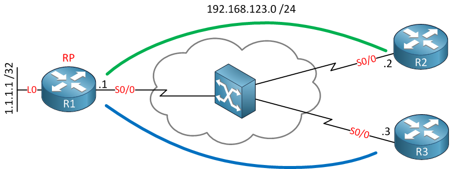
Let me show you the topology that I will use to explain and demonstrate this to you:
multicast ip nbma mode example
Above you see 3 routers. R1 is the hub router, R2 and R3 are my spokes. We are using point-to-multipoint frame-relay so there is only a single subnet. R1 is also the RP (Rendezvous Point)
PIM treats our frame-relay network as a broadcast media. It expects that all routers can hear each other directly. This however is only true when we have a full mesh…using a hub and spoke topology like the network above this doesn’t apply because there is only a PVC between the hub and spoke routers. The spoke routers are unable to reach each other directly, they have to go through the hub router.
This causes a number of issues. First of all, whenever a spoke router sends a multicast packet it will be received by the hub router, but the hub router doesn’t forward it to other spoke routers because of the RPF rule (never send a packet out of the interface you received it on). One of the methods of dealing with this problem is by using point-to-point sub-interfaces as its solves the split horizon problem.
The other problem is that spoke routers don’t hear each others PIM messages. For example, let’s say that R2 and R3 are both receiving a certain multicast stream. After awhile there are no users behind R2 that are interested in this stream and as a result R2 will send a PIM prune message to R1.
If R3 still has active receivers it would normally send a PIM override message to let R1 know that we still want to keep receiving the multicast stream. R1 however assumes that the prune message from R2 is heard by all PIM routers but this is not the case in our hub and spoke topology…only the hub router has received it, R3 never heard this PIM prune message. As a result R1 will prune the multicast stream and R3 will not receive anything anymore…
PIM NBMA mode solves these issues that I just described to you. Basically it will tell PIM that the frame-relay network should be treated as a collection of point-to-point links, not as a multi-access network.  Let’s take a look at the example above and configure it so you can see how it works.
OSPF has been configured to advertise the loopback0 interface of R1 so that we can use it as the IP address for the RP. Let’s start by enabling PIM on the interfaces:
R1(config)#interface serial 0/0
R1(config-if)#ip pim sparse-mode
R2(config)#interface serial 0/0
R2(config-if)#ip pim sparse-mode 
R3(config-if)#interface serial 0/0
R3(config-if)#ip pim sparse-mode
This will activate PIM on all serial interfaces. Let’s verify that we have PIM neighbors:
R1#show ip pim neighbor 
PIM Neighbor Table
Mode: B - Bidir Capable, DR - Designated Router, N - Default DR Priority,
      S - State Refresh Capable
Neighbor          Interface                Uptime/Expires    Ver   DR
Address                                                            Prio/Mode
192.168.123.3     Serial0/0                00:03:51/00:01:21 v2    1 / DR S
192.168.123.2     Serial0/0                00:04:04/00:01:35 v2    1 / S
That’s looking good. Now let’s configure the RP:
R1(config)#ip pim rp-address 1.1.1.1
R2(config)#ip pim rp-address 1.1.1.1
R3(config)#ip pim rp-address 1.1.1.1
I will use a static RP as it saves the hassle configuring auto-RP and a mapping agent. Let’s configure R3 as a receiver for the 239.1.1.2 multicast group address, I will use R2 as a source by sending pings:
R3(config-if)#ip igmp join-group 239.1.1.2
R2#ping 239.1.1.2 repeat 9999

Type escape sequence to abort.
Sending 9999, 100-byte ICMP Echos to 239.1.1.2, timeout is 2 seconds:
.....
As you can see nothing no packets are arriving. Let’s take a closer look to see what is going on:
R3#show ip mroute 239.1.1.2
IP Multicast Routing Table
Flags: D - Dense, S - Sparse, B - Bidir Group, s - SSM Group, C - Connected,
       L - Local, P - Pruned, R - RP-bit set, F - Register flag,
       T - SPT-bit set, J - Join SPT, M - MSDP created entry,
       X - Proxy Join Timer Running, A - Candidate for MSDP Advertisement,
       U - URD, I - Received Source Specific Host Report,
       Z - Multicast Tunnel, z - MDT-data group sender,
       Y - Joined MDT-data group, y - Sending to MDT-data group
Outgoing interface flags: H - Hardware switched, A - Assert winner
 Timers: Uptime/Expires
 Interface state: Interface, Next-Hop or VCD, State/Mode

(*, 239.1.1.2), 00:01:40/00:02:27, RP 1.1.1.1, flags: SJPCL
  Incoming interface: Serial0/0, RPF nbr 192.168.123.1
  Outgoing interface list: Null
R3 has registered itself at the RP but doesn’t receive anything.
R1#show ip mroute 239.1.1.2
IP Multicast Routing Table
Flags: D - Dense, S - Sparse, B - Bidir Group, s - SSM Group, C - Connected,
       L - Local, P - Pruned, R - RP-bit set, F - Register flag,
       T - SPT-bit set, J - Join SPT, M - MSDP created entry,
       X - Proxy Join Timer Running, A - Candidate for MSDP Advertisement,
       U - URD, I - Received Source Specific Host Report,
       Z - Multicast Tunnel, z - MDT-data group sender,
       Y - Joined MDT-data group, y - Sending to MDT-data group
Outgoing interface flags: H - Hardware switched, A - Assert winner
 Timers: Uptime/Expires
 Interface state: Interface, Next-Hop or VCD, State/Mode

(*, 239.1.1.2), 00:02:10/00:03:18, RP 1.1.1.1, flags: SJC
  Incoming interface: Null, RPF nbr 0.0.0.0
  Outgoing interface list:
    Serial0/0, Forward/Sparse, 00:02:10/00:03:18

(192.168.123.2, 239.1.1.2), 00:01:38/00:02:00, flags: PJT
  Incoming interface: Serial0/0, RPF nbr 0.0.0.0
  Outgoing interface list: Null
R1 is receiving traffic from R2 but doesn’t forward it out of the same interface to R3 (Serial0/0).
Let’s enable IP PIM NBMA mode on R1 now:
R1(config)#interface serial 0/0
R1(config-if)#ip pim nbma-mode 
Suddenly the pings start working:
R2#ping 239.1.1.2 repeat 9999

Type escape sequence to abort.
Sending 9999, 100-byte ICMP Echos to 239.1.1.2, timeout is 2 seconds:

Reply to request 0 from 192.168.123.3, 4 ms
Reply to request 1 from 192.168.123.3, 1 ms
And you can see the difference here in the multicast routing table of R1:
R1#show ip mroute 239.1.1.2
IP Multicast Routing Table
Flags: D - Dense, S - Sparse, B - Bidir Group, s - SSM Group, C - Connected,
       L - Local, P - Pruned, R - RP-bit set, F - Register flag,
       T - SPT-bit set, J - Join SPT, M - MSDP created entry,
       X - Proxy Join Timer Running, A - Candidate for MSDP Advertisement,
       U - URD, I - Received Source Specific Host Report,
       Z - Multicast Tunnel, z - MDT-data group sender,
       Y - Joined MDT-data group, y - Sending to MDT-data group
Outgoing interface flags: H - Hardware switched, A - Assert winner
 Timers: Uptime/Expires
 Interface state: Interface, Next-Hop or VCD, State/Mode

(*, 239.1.1.2), 00:04:20/00:03:06, RP 1.1.1.1, flags: SJC
  Incoming interface: Null, RPF nbr 0.0.0.0
  Outgoing interface list:
    Serial0/0, 192.168.123.3, Forward/Sparse, 00:00:23/00:03:06

(192.168.123.2, 239.1.1.2), 00:03:48/00:03:28, flags: JT
  Incoming interface: Serial0/0, RPF nbr 0.0.0.0
  Outgoing interface list:
    Serial0/0, 192.168.123.3, Forward/Sparse, 00:00:23/00:03:06
Above you see that it added the Serial0/0 interface to the list of outgoing interfaces.
And finally let’s check the multicast routing table of R3:
R3#show ip mroute 239.1.1.2
IP Multicast Routing Table
Flags: D - Dense, S - Sparse, B - Bidir Group, s - SSM Group, C - Connected,
       L - Local, P - Pruned, R - RP-bit set, F - Register flag,
       T - SPT-bit set, J - Join SPT, M - MSDP created entry,
       X - Proxy Join Timer Running, A - Candidate for MSDP Advertisement,
       U - URD, I - Received Source Specific Host Report,
       Z - Multicast Tunnel, z - MDT-data group sender,
       Y - Joined MDT-data group, y - Sending to MDT-data group
Outgoing interface flags: H - Hardware switched, A - Assert winner
 Timers: Uptime/Expires
 Interface state: Interface, Next-Hop or VCD, State/Mode

(*, 239.1.1.2), 00:04:13/stopped, RP 1.1.1.1, flags: SJPCLF
  Incoming interface: Serial0/0, RPF nbr 192.168.123.1
  Outgoing interface list: Null

(192.168.123.2, 239.1.1.2), 00:00:16/00:02:59, flags: PLFT
  Incoming interface: Serial0/0, RPF nbr 0.0.0.0
  Outgoing interface list: Null
You can see that it receives the pings from 192.168.123.2 on its serial0/0 interface now.
hostname R1
!
ip cef
!
interface Loopback0
 ip address 1.1.1.1 255.255.255.255
!
interface Serial0/0/0
 ip address 192.168.123.1 255.255.255.0
 ip pim nbma-mode
 ip pim sparse-mode
 no fair-queue
!
ip pim rp-address 1.1.1.1
!
end
hostname R2
!
ip cef
!
interface Serial0/0/0
 ip address 192.168.123.2 255.255.255.0
 ip pim sparse-mode
 no fair-queue
!
ip pim rp-address 1.1.1.1
!
end
hostname R3
!
ip cef
!
interface Serial0/0/0
 ip address 192.168.123.3 255.255.255.0
 ip pim sparse-mode
 ip igmp join-group 239.1.1.2
!
ip pim rp-address 1.1.1.1
!
end

That’s all there is to it! I hope this has been helpful to you, if you have any more questions feel free to leave a comment!

Multicast Auto-RP Mapping Agent behind Spoke

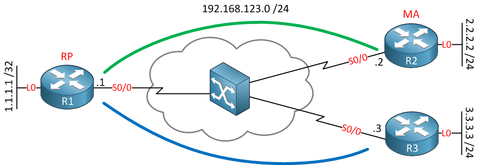
Multicast itself can be tricky enough but the real fun starts when you try to run it over a network like frame-relay. One of the scenarios you can encounter is having a mapping agent behind one of the spokes, you will discover that only the hub router will receive the auto-rp information from the mapping agent, not the other spokes. Let me show you an example what will go wrong and how to fix it. This is the topology we’ll be using:
Multicast Hub and Spoke
Above you see a frame-relay network with a hub (R1) and two spokes (R2 and R3). This network has been configured as frame-relay point-to-multipoint. Our routers will believe that we have full reachability but in reality there are only two PVCs, this is a classical hub and spoke topology. Each router has a loopback0 interface which is advertised in OSPF for reachability.
R1 will be configured as our RP (Rendezvous Point) and R2 will be our mapping agent. In this scenario you will see that R3 will never receive the information from the mapping agent and won’t learn that R1 is the RP. Here is our configuration:
R1(config)#ip multicast-routing 
R2(config)#ip multicast-routing 
R3(config)#ip multicast-routing 
First of all we will enable multicast routing on all routers, if you forget this multicast won’t work at all…
Since I am using some loopback interfaces, we’ll need some routing. I will use EIGRP to advertise all interfaces:
R1(config)#router eigrp 1
R1(config-router)#no auto-summary 
R1(config-router)#network 192.168.123.0
R1(config-router)#network 1.0.0.0
R2(config)#router eigrp 1
R2(config-router)#no auto-summary
R2(config-router)#network 2.0.0.0
R2(config-router)#network 192.168.123.0
R3(config)#router eigrp 1
R3(config-router)#no auto-summary 
R3(config-router)#network 192.168.123.0
R3(config-router)#network 3.0.0.0
R1(config)#interface serial 0/0
R1(config-if)#ip pim sparse-dense-mode 
R2(config)#interface serial 0/0
R2(config-if)#ip pim sparse-dense-mode 
R3(config)#interface serial 0/0
R3(config-if)#ip pim sparse-dense-mode 
On all routers we will enable sparse-dense mode. This means that we will use sparse mode if possible, if there is no RP we will use dense mode. This means that the multicast groups 224.1.0.39 and 224.1.0.40 will be forwarded with dense mode. Keep in mind that 224.1.0.40 is used by mapping agents to forward the RP-to-group information to other routers.
R1#show ip pim neighbor 
PIM Neighbor Table
Mode: B - Bidir Capable, DR - Designated Router, N - Default DR Priority,
      S - State Refresh Capable
Neighbor          Interface                Uptime/Expires    Ver   DR
Address                                                            Prio/Mode
192.168.123.3     Serial0/0                00:02:10/00:01:32 v2    1 / DR S
192.168.123.2     Serial0/0                00:02:16/00:01:28 v2    1 / S
A quick check doesn’t hurt…on R1 we can see that R2 and R3 are PIM neighbors. Let’s configure R1 as a rendezvous point:
R1(config)#interface loopback 0
R1(config-if)#ip pim sparse-dense-mode 
R1(config)#ip pim send-rp-announce loopback 0 scope 10
I will use the loopback0 interface as the source IP address for the RP. Here you can see that R1 is a working RP:
R1#show ip pim rp mapping 
PIM Group-to-RP Mappings
This system is an RP (Auto-RP)
Now let’s configure that mapping agent on R2:
R2(config)#interface loopback 0
R2(config-if)#ip pim sparse-dense-mode
R2(config)#ip pim send-rp-discovery loopback 0 scope 10
I will configure the loopback0 interface to use for the mapping agent. Let’s verify our work:
R2#show ip pim rp mapping 
PIM Group-to-RP Mappings
This system is an RP-mapping agent (Loopback0)

Group(s) 224.0.0.0/4
  RP 1.1.1.1 (?), v2v1
    Info source: 1.1.1.1 (?), elected via Auto-RP
         Uptime: 00:00:17, expires: 00:02:41
This is looking good. R2 is the mapping agent and it has discovered R1 as a rendezvous point. Let’s take a look at the multicast routing table:
R2#show ip mroute 224.0.1.39
IP Multicast Routing Table
Flags: D - Dense, S - Sparse, B - Bidir Group, s - SSM Group, C - Connected,
L - Local, P - Pruned, R - RP-bit set, F - Register flag,
T - SPT-bit set, J - Join SPT, M - MSDP created entry,
X - Proxy Join Timer Running, A - Candidate for MSDP Advertisement,
U - URD, I - Received Source Specific Host Report,
Z - Multicast Tunnel, z - MDT-data group sender,
Y - Joined MDT-data group, y - Sending to MDT-data group
Outgoing interface flags: H - Hardware switched, A - Assert winner
Timers: Uptime/Expires
Interface state: Interface, Next-Hop or VCD, State/Mode

(*, 224.0.1.39), 00:08:18/stopped, RP 0.0.0.0, flags: DCL
Incoming interface: Null, RPF nbr 0.0.0.0
Outgoing interface list:
Loopback0, Forward/Sparse-Dense, 00:05:54/00:00:00
Serial0/0, Forward/Sparse-Dense, 00:08:18/00:00:00

(1.1.1.1, 224.0.1.39), 00:08:18/00:02:42, flags: LT
Incoming interface: Serial0/0, RPF nbr 192.168.123.1
Outgoing interface list:
Loopback0, Forward/Sparse-Dense, 00:05:54/00:00:00
Above you can see that our mapping agent has received information from the RP because IP address 1.1.1.1 (loopback 0 interface of R1) is sending towards multicast group address 224.0.1.39. Let’s see if our mapping agent is advertising this to other routers:
R2#show ip mroute 224.0.1.40
IP Multicast Routing Table
Flags: D - Dense, S - Sparse, B - Bidir Group, s - SSM Group, C - Connected,
       L - Local, P - Pruned, R - RP-bit set, F - Register flag,
       T - SPT-bit set, J - Join SPT, M - MSDP created entry,
       X - Proxy Join Timer Running, A - Candidate for MSDP Advertisement,
       U - URD, I - Received Source Specific Host Report,
       Z - Multicast Tunnel, z - MDT-data group sender,
       Y - Joined MDT-data group, y - Sending to MDT-data group
Outgoing interface flags: H - Hardware switched, A - Assert winner
 Timers: Uptime/Expires
 Interface state: Interface, Next-Hop or VCD, State/Mode

(*, 224.0.1.40), 00:08:11/stopped, RP 0.0.0.0, flags: DCL
  Incoming interface: Null, RPF nbr 0.0.0.0
  Outgoing interface list:
    Loopback0, Forward/Sparse-Dense, 00:02:13/00:00:00
    Serial0/0, Forward/Sparse-Dense, 00:08:11/00:00:00

(2.2.2.2, 224.0.1.40), 00:01:38/00:02:21, flags: LT
  Incoming interface: Loopback0, RPF nbr 0.0.0.0
  Outgoing interface list:
    Serial0/0, Forward/Sparse-Dense, 00:01:38/00:00:00
This is looking good too. The mapping agent is sending the RP-to-Group information towards 224.0.1.40. It’s outgoing interface is the serial0/0 interface. Now let’s check the RP:
R1#show ip mroute 224.0.1.40
IP Multicast Routing Table
Flags: D - Dense, S - Sparse, B - Bidir Group, s - SSM Group, C - Connected,
       L - Local, P - Pruned, R - RP-bit set, F - Register flag,
       T - SPT-bit set, J - Join SPT, M - MSDP created entry,
       X - Proxy Join Timer Running, A - Candidate for MSDP Advertisement,
       U - URD, I - Received Source Specific Host Report,
       Z - Multicast Tunnel, z - MDT-data group sender,
       Y - Joined MDT-data group, y - Sending to MDT-data group
Outgoing interface flags: H - Hardware switched, A - Assert winner
 Timers: Uptime/Expires
 Interface state: Interface, Next-Hop or VCD, State/Mode

(*, 224.0.1.40), 00:16:00/stopped, RP 0.0.0.0, flags: DCL
  Incoming interface: Null, RPF nbr 0.0.0.0
  Outgoing interface list:
    Serial0/0, Forward/Sparse-Dense, 00:16:00/00:00:00

(2.2.2.2, 224.0.1.40), 00:08:48/00:02:09, flags: PLT
  Incoming interface: Serial0/0, RPF nbr 192.168.123.2
  Outgoing interface list: Null
Above you see that the RP receives information from the mapping agent but it’s not forwarding 224.0.1.40 out of its interfaces. Since R1 is the hub router it will not forward traffic out of the same interface to other spoke routers(split horizon rule). Let’s see what R3 thinks about all this:
R3#show ip mroute 224.0.1.40
IP Multicast Routing Table
Flags: D - Dense, S - Sparse, B - Bidir Group, s - SSM Group, C - Connected,
       L - Local, P - Pruned, R - RP-bit set, F - Register flag,
       T - SPT-bit set, J - Join SPT, M - MSDP created entry,
       X - Proxy Join Timer Running, A - Candidate for MSDP Advertisement,
       U - URD, I - Received Source Specific Host Report,
       Z - Multicast Tunnel, z - MDT-data group sender,
       Y - Joined MDT-data group, y - Sending to MDT-data group
Outgoing interface flags: H - Hardware switched, A - Assert winner
 Timers: Uptime/Expires
 Interface state: Interface, Next-Hop or VCD, State/Mode

(*, 224.0.1.40), 00:17:36/00:02:58, RP 0.0.0.0, flags: DCL
  Incoming interface: Null, RPF nbr 0.0.0.0
  Outgoing interface list:
    Serial0/0, Forward/Sparse-Dense, 00:17:36/00:00:00
As you can see R3 doesn’t receive anything from the 224.0.1.40 multicast group address. It doesn’t learn any RPs:
R3#show ip pim rp mapping
PIM Group-to-RP Mappings
Use show ip pim rp mapping and you’ll find out that it doesn’t know any rendezvous points. In order to fix this there are multiple solutions:
  • Get rid of the point-to-multipoint interfaces and use sub-interfaces. This will allow the hub router to forward multicast to all spoke routers since we are using different interfaces to send and receive traffic.
  • Move the mapping agent to a router above the hub router, make sure it’s not behind a spoke router.
  • Create a tunnel between the spoke routers so that they can learn directly from each other.
I will use the tunnel solution to solve this problem. We will create a tunnel between R2 and R3 so that R3 can learn from the mapping agent directly. Here’s what the configuration looks like:
R2(config)#interface tunnel 0
R2(config-if)#tunnel source loopback 0
R2(config-if)#tunnel destination 3.3.3.3
R2(config-if)#ip address 192.168.23.2 255.255.255.0
R2(config-if)#ip pim sparse-dense-mode
R3(config)#interface tunnel 0
R3(config-if)#tunnel source loopback 0
R3(config-if)#tunnel destination 2.2.2.2
R3(config-if)#ip address 192.168.23.3 255.255.255.0
R3(config-if)#ip pim sparse-dense-mode
Don’t forget to enable PIM on the tunnel interfaces. Let’s take another look at R3 to see if it learns anything:
R3#show ip mroute 224.0.1.40
IP Multicast Routing Table
Flags: D - Dense, S - Sparse, B - Bidir Group, s - SSM Group, C - Connected,
       L - Local, P - Pruned, R - RP-bit set, F - Register flag,
       T - SPT-bit set, J - Join SPT, M - MSDP created entry,
       X - Proxy Join Timer Running, A - Candidate for MSDP Advertisement,
       U - URD, I - Received Source Specific Host Report,
       Z - Multicast Tunnel, z - MDT-data group sender,
       Y - Joined MDT-data group, y - Sending to MDT-data group
Outgoing interface flags: H - Hardware switched, A - Assert winner
 Timers: Uptime/Expires
 Interface state: Interface, Next-Hop or VCD, State/Mode

(*, 224.0.1.40), 00:29:47/stopped, RP 0.0.0.0, flags: DCL
  Incoming interface: Null, RPF nbr 0.0.0.0
  Outgoing interface list:
    Tunnel0, Forward/Sparse-Dense, 00:01:12/00:00:00
    Serial0/0, Forward/Sparse-Dense, 00:29:47/00:00:00

(2.2.2.2, 224.0.1.40), 00:00:26/00:02:33, flags: L
  Incoming interface: Serial0/0, RPF nbr 192.168.123.1
  Outgoing interface list:
    Tunnel0, Forward/Sparse-Dense, 00:00:26/00:00:00
Now we are learning but something is still not quite right.  We learn this information through the tunnel interface but the RPF neighbor shows 192.168.123.1. Let’s enable a debug so I can show you something:
R3#debug ip mpacket   
IP multicast packets debugging is on

IP(0): s=2.2.2.2 (Tunnel0) d=224.0.1.40 id=936, ttl=9, prot=17, len=48(48), not RPF interface
If you enable the debug, you’ll see the message above. It says that the tunnel0 interface is not the RPF interface.
Be aware that you might have to disable route caching or you won’t see any multicast debug information. Use the “no ip mroute-cache” command on the interface to disable it.
You can also spot RPF errors using the following command:
R3#show ip rpf 2.2.2.2
RPF information for ? (2.2.2.2)
  RPF interface: Serial0/0
  RPF neighbor: ? (192.168.123.1)
  RPF route/mask: 2.2.2.2/32
  RPF type: unicast (ospf 1)
  RPF recursion count: 0
  Doing distance-preferred lookups across tables
The debug and the show ip rpf command both show us that the RPF neighbor is 192.168.123.2. This has to be changed to the tunnel interface…we need to fix this RPF error:
R3(config)#ip mroute 2.2.2.2 255.255.255.255 tunnel 0
We will create a static multicast route for the mapping agent pointing to the tunnel interface to solve our RPF error.
Keep in mind that the RPF check applies to data and control plane traffic. I’m creating a static multicast route to solve the RPF error for the mapping agent since we learn about the RP through the tunnel interface. Multicast data packets will be sent over the serial link.
Let’s take a look at the multicast routing table again:
R3#show ip mroute 224.0.1.40
IP Multicast Routing Table
Flags: D - Dense, S - Sparse, B - Bidir Group, s - SSM Group, C - Connected,
       L - Local, P - Pruned, R - RP-bit set, F - Register flag,
       T - SPT-bit set, J - Join SPT, M - MSDP created entry,
       X - Proxy Join Timer Running, A - Candidate for MSDP Advertisement,
       U - URD, I - Received Source Specific Host Report,
       Z - Multicast Tunnel, z - MDT-data group sender,
       Y - Joined MDT-data group, y - Sending to MDT-data group
Outgoing interface flags: H - Hardware switched, A - Assert winner
 Timers: Uptime/Expires
 Interface state: Interface, Next-Hop or VCD, State/Mode

(*, 224.0.1.40), 00:38:49/stopped, RP 0.0.0.0, flags: DCL
  Incoming interface: Null, RPF nbr 0.0.0.0
  Outgoing interface list:
    Tunnel0, Forward/Sparse-Dense, 00:10:15/00:00:00
    Serial0/0, Forward/Sparse-Dense, 00:38:49/00:00:00

(2.2.2.2, 224.0.1.40), 00:02:29/00:02:34, flags: LT
  Incoming interface: Tunnel0, RPF nbr 192.168.23.2, Mroute
  Outgoing interface list:
    Serial0/0, Forward/Sparse-Dense, 00:00:44/00:00:00
Now it shows the tunnel0 interface as the RPF neighbor which is what we are looking for. Let’s do a little test to see if multicast is working now:
R3(config)#interface loopback 0
R3(config-if)#ip pim sparse-dense-mode 
R3(config-if)#ip igmp join-group 239.1.1.1
I will join the 239.1.1.1 multicast group address on R3, now let’s generate some traffic:
R2#ping 239.1.1.1           

Type escape sequence to abort.
Sending 1, 100-byte ICMP Echos to 239.1.1.1, timeout is 2 seconds:

Reply to request 0 from 192.168.23.3, 4 ms
I’ll send some pings from R2 and you can see that R3 is responding…problem solved!
hostname R1
!
ip cef
!
ip multicast-routing
!
interface Loopback0
 ip address 1.1.1.1 255.255.255.255
 ip pim sparse-dense-mode
!
interface Serial0/0
 ip address 192.168.123.1 255.255.255.0
 ip pim sparse-dense-mode
!
ip pim send-rp-announce Loopback0 scope 10
!
end
hostname R2
!
ip cef
!
ip multicast-routing
!
interface Loopback0
 ip address 2.2.2.2 255.255.255.0
 ip pim sparse-dense-mode
!
interface Tunnel0
 ip address 192.168.23.2 255.255.255.0
 ip pim sparse-dense-mode
 tunnel source Loopback0
 tunnel destination 3.3.3.3
!
interface Serial0/0
 ip address 192.168.123.2 255.255.255.0
 ip pim sparse-dense-mode
!
ip pim send-rp-discovery Loopback0 scope 10
!
end
hostname R3
!
ip cef
!
ip multicast-routing
!
interface Loopback0
 ip address 3.3.3.3 255.255.255.0
 ip pim sparse-dense-mode
 ip igmp join-group 239.1.1.1
!
interface Tunnel0
 ip address 192.168.23.3 255.255.255.0
 ip pim sparse-dense-mode
 tunnel source Loopback0
 tunnel destination 2.2.2.2
!
interface Serial0/0
 ip address 192.168.123.3 255.255.255.0
 ip pim sparse-dense-mode
 no fair-queue
!
ip mroute 2.2.2.2 255.255.255.255 Tunnel0
!
end
I hope that this lesson is useful to you, if you have any questions please leave a comment!

Multicast PIM Accept Register

By default all sources are allowed to register at the RP (Rendezvous Point) when using PIM sparse mode. When a new source starts sending traffic to a multicast group address, the PIM DR (Designated Router) on the segment connected to the source will forward a PIM register message to the RP.
This PIM register message contains the original multicast packet from the source, and it includes the IP address of the source and the destination multicast group address. We can configure our RP to filter certain sources, if we do this the RP will send a PIM register-stop message to the PIM DR so that it will not build the SPT towards the source.
Let’s take a look at an example topology:
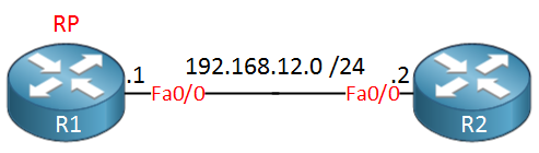
R1 rendezvous point R2 source
Above we have two routers, R1 and R2. We will configure R1 as a rendezvous point and R2 will be our source. Let’s configure the basics first:
R1(config)#ip multicast-routing          
R1(config)#ip pim rp-address 192.168.12.1
R1(config)#interface fastEthernet 0/0    
R1(config-if)#ip pim sparse-mode
R2(config)#ip multicast-routing 
R2(config)#ip pim rp-address 192.168.12.1
R2(config)#interface fastEthernet 0/0
R2(config-if)#ip pim sparse-mode 
Just a simple PIM sparse mode setup where R1 is the RP. By default all sources and all multicast groups are allowed to register at the RP.
Let’s send some traffic to a multicast group address from R2 to see what R1 thinks of it:
R1#debug ip pim
PIM debugging is on
First we will enable a debug on R1, now let’s send some traffic from R2:
R2#ping 239.1.1.1 repeat 9999

Type escape sequence to abort.
Sending 9999, 100-byte ICMP Echos to 239.1.1.1, timeout is 2 seconds:
...
This is what you will see on R1:
R1#
PIM(0): Received v2 Register on FastEthernet0/0 from 192.168.12.2
It receives a PIM register message from 192.168.12.2. Nobody is listening to this multicast stream but you will find it in the multicast routing table:
R1#show ip mroute 239.1.1.1
IP Multicast Routing Table
Flags: D - Dense, S - Sparse, B - Bidir Group, s - SSM Group, C - Connected,
       L - Local, P - Pruned, R - RP-bit set, F - Register flag,
       T - SPT-bit set, J - Join SPT, M - MSDP created entry,
       X - Proxy Join Timer Running, A - Candidate for MSDP Advertisement,
       U - URD, I - Received Source Specific Host Report,
       Z - Multicast Tunnel, z - MDT-data group sender,
       Y - Joined MDT-data group, y - Sending to MDT-data group
Outgoing interface flags: H - Hardware switched, A - Assert winner
 Timers: Uptime/Expires
 Interface state: Interface, Next-Hop or VCD, State/Mode

(*, 239.1.1.1), 00:01:28/stopped, RP 192.168.12.1, flags: SP
  Incoming interface: Null, RPF nbr 0.0.0.0
  Outgoing interface list: Null

(192.168.12.2, 239.1.1.1), 00:01:28/00:02:58, flags: PT
  Incoming interface: FastEthernet0/0, RPF nbr 0.0.0.0
  Outgoing interface list: Null
Above you see that 192.168.12.2 has been added as a source for 239.1.1.1. Now let’s configure a filter so that we reject 192.168.12.2 as a source for this multicast group:
R1(config)#ip pim accept-register list SOURCES
R1(config)#ip access-list extended SOURCES 
R1(config-ext-nacl)#deny ip host 192.168.12.2 host 239.1.1.1
R1(config-ext-nacl)#permit ip host 192.168.12.2 any 
We can use the IP PIM accept-register command to filter sources that we don’t want. In the example above I created an access-list that will reject 192.168.12.2 as the source for multicast group 239.1.1.1. Everything else is allowed. Let’s send some traffic from R2 to see what is going on:
R2#ping 239.1.1.1 repeat 9999

Type escape sequence to abort.
Sending 9999, 100-byte ICMP Echos to 239.1.1.1, timeout is 2 seconds:
...
R1#
PIM(0): Received v2 Register on FastEthernet0/0 from 192.168.12.2
     for 192.168.12.2, group 239.1.1.1
%PIM-4-INVALID_SRC_REG: Received Register from 192.168.12.2 for (192.168.12.2, 239.1.1.1), not willing to be RP
R1#
PIM(0): Register for 192.168.12.2, group 239.1.1.1 rejected
PIM(0): Send v2 Register-Stop to 192.168.12.2 for 192.168.12.2, group 239.1.1.1
You can see that R1 doesn’t accept this PIM register message and as a result it will send a PIM register-stop message. That’s how you can filter sources to register at your RP.
hostname R1
!
ip cef
!
ip multicast-routing
!
interface FastEthernet0/0
 ip address 192.168.12.1 255.255.255.0
 ip pim sparse-mode
!
ip pim rp-address 192.168.12.1
ip pim accept-register list SOURCES
!
ip access-list extended SOURCES
 deny   ip host 192.168.12.2 host 239.1.1.1
 permit ip host 192.168.12.2 any
!
end
hostname R2
!
ip cef
!
ip multicast-routing
!
interface FastEthernet0/0
 ip address 192.168.12.2 255.255.255.0
 ip pim sparse-mode
!
ip pim rp-address 192.168.12.1
!
end

I hope this has been helpful to you, if you have any questions feel free to ask!

Multicast PIM Accept RP

PIM Accept RP is a security feature on Cisco IOS routers that prevents unwanted rendezvous points or multicast groups to become activate in the PIM sparse mode domain. By default a RP will accept all multicast groups in the 224.0.0.0/4 range (the entire class D range) but if we want we can configure our router to allow only PIM join/prune messages towards the groups that we want.
Let me demonstrate this feature using a very simple topology:
R1 R2 Fastethernet Interfaces
Only 2 routers, R1 will be our rendezvous point. Let’s configure this network so that PIM sparse mode is enabled and R1 becomes the RP:
R1(config)#ip multicast-routing          
R1(config)#ip pim rp-address 192.168.12.1
R1(config)#interface fastEthernet 0/0    
R1(config-if)#ip pim sparse-mode 
R2(config)#ip multicast-routing 
R2(config)#ip pim rp-address 192.168.12.1
R2(config)#interface fastEthernet 0/0
R2(config-if)#ip pim sparse-mode 
This is how we enable multicast routing, configure R1 as the RP and enable sparse mode. Let’s take a look what multicast groups R1 will serve:
R1#show ip pim rp mapping 
PIM Group-to-RP Mappings

Group(s): 224.0.0.0/4, Static
    RP: 192.168.12.1 (?)
R2#show ip pim rp mapping 
PIM Group-to-RP Mappings

Group(s): 224.0.0.0/4, Static
    RP: 192.168.12.1 (?)
Both routers agree that R1 is the RP for the entire multicast group range 224.0.0.0/4. Let’s change it so that it only accepts multicast group 239.1.1.1:
R1(config)#ip pim accept-rp 192.168.12.1 GROUPS

R1(config)#ip access-list standard GROUPS
R1(config-std-nacl)#permit 239.1.1.1
The ip pim accept-rp command lets us define what groups we want to be the RP for. Let’s test to see if it works:
R2(config)#interface fastEthernet 0/0
R2(config-if)#ip igmp join-group 239.2.2.2
We will configure R2 to join multicast group address 239.2.2.2. Let’s see what R1 thinks of it:

R1#               
%PIM-6-INVALID_RP_JOIN: Received (*, 239.2.2.2) Join from 192.168.12.2 for invalid RP 192.168.12.1
As you can see above it is being rejected. Keep in mind that this command is not a “RP” command, it can be configured on all PIM enabled routers in your network. If you only configure it on the RP then unwanted PIM join messages can traverse the network but they will be dropped at the RP. If you don’t want this then you should configure this on all PIM enabled routers in your network.
hostname R1
!
ip cef
!
ip multicast-routing
!
interface FastEthernet0/0
 ip address 192.168.12.2 255.255.255.0
 ip pim sparse-mode
!
ip pim rp-address 192.168.12.1
ip pim accept-rp 192.168.12.1 GROUPS
!
ip access-list standard GROUPS
 permit 239.1.1.1
!
end
hostname R2
!
ip cef
!
ip multicast-routing
!
interface FastEthernet0/0
 ip address 192.168.12.3 255.255.255.0
 ip pim sparse-mode
 ip igmp join-group 239.2.2.2
!
ip pim rp-address 192.168.12.1
!
end


That’s all there is to it! If you have any questions feel free to ask.