Showing posts with label SPAN. Show all posts

Saturday, December 11, 2021

ASR9000/XR: How to use Port Spanning or Port Mirroring


Introduction

This document provides some extra documentation and use cases on the use of port spanning or port mirroring.

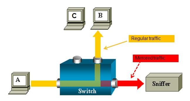
You can monitor traffic passing in & out of a set of L2 or L3 Ethernet interfaces (including bundle-Ether).
 

span1.JPG

Core Issue

ASR 9000 is the only platform implementing SPAN on XR (Only support on ethernet linecards, not on SIP-700.)


You can use SPAN/Mirror in the follow scenarios

- L2 & L3 interfaces.
- Local,  R-SPAN, and PW-SPAN only (no ER SPAN.)
- Scale limits:
    8 monitor sessions
    800 total source ports
    1.5 Gig bidirectional replication limit toward fabric for bundle interfaces and 10 Gig ports.
    Guideline:  ~ 10% - 15% total bandwidth can be mirrored system-wide
- Source ports:  Physical, EFPs, and bundles interfaces (L2 & L3)
- Destination ports:  Ethernet interfaces, EFPs, and PW-SPAN. (No bundle) [ only L2 transport interfaces are supported as destination ports]

- Ability to use ACL's to define which traffic is to be captured

- Capture multicast traffic is possible


Note: some of the functionality mentioned are enhancements to the XR 4.0.1 release, this document assumes you are using this release or later.


A good reference on the terminology of SPAN/Mirror can be found here:

http://www.cisco.com/en/US/docs/switches/lan/catalyst6500/ios/12.2SX/configuration/guide/span.pdf


SPAN order of operation

SPAN mirrors what is on the wire
For ingress, this means packets are mirrored before QOS, ACL, and encapsulation rewrite operations.
For egress, this means packets are mirrored after QOS, ACL, and encapsulation rewrite operations.


Partial Packet Mirroring

User can configure to mirror first 64 upto 256 bytes of the packet.
Note: The actual mirrored packet will be the configured size plus 4-byte trailling CRC.


Sample config:


interface GigabitEthernet0/6/0/20 l2transport
  monitor-session PW
  mirror first 100  <==  valid range: [64, 256], inclusively
  !
!


Note:  The mirrored packet received at sniffer will have the size of 104
               (4-byte of trailing CRC added by transmit MAC layer.)


ACL based Mirroring


“permit/deny” determines the behavior of the regular traffic (forwarded or dropped)
capture” determines whether the packet is mirrored to the SPAN destination.


On SPAN: mirror traffic on the wire (regardless with or without ACL.)

      ACL on ingress direction:
           SPAN will mirror traffic even regular traffic dropped by ACL:  Always mirror!
     ACL on egress direction
          Will mirror if regular traffic is forwarded (Permit)
          Will not mirror if regular traffic is dropped (Deny.)


Inconsistent configurations:
“acl” is configured on SPAN source port but
   ACL has no “capture” keyword:
    No traffic gets mirrored. 
“acl” is NOT configured on SPAN source port but
   ACL has “capture” keyword:
    Mirroring traffic as normal, no ACL performed.


The ACL can also be an L2 ACL :


ethernet-services access-list esacl_t2
10 deny 1234.5678.90ab 0000.0000.0000 any capture


L3 Spanning Example


monitor-session TEST
destination interface GigabitEthernet0/1/0/2 (<<<< this is NP3)
!
interface GigabitEthernet0/1/0/14  (<<<< this is NP2)
ipv4 address 5.5.1.1 255.255.255.0
monitor-session TEST
  acl
!
load-interval 30
ipv4 access-group span ingress
!
ipv4 access-list span
10 permit ipv4 any host 1.1.1.10 capture
15 permit ipv4 any host 239.1.1.1 capture
20 permit ipv4 any host 2.2.2.100
30 permit ipv4 any any


Sample TRAFFIC GEN: (sending multicast in this example)
tgn rate 1000
L2-dest-addr 0100.5E01.0101
L2-src-addr 0003.A0FD.28A8
L3-src-addr 5.5.1.2
L3-dest-addr 239.1.1.1


Checking NP2(the port that we are spanning)
Show global stats counters for NP2, revision v3


Read 12 non-zero NP counters:
Offset  Counter                                         FrameValue   Rate (pps)
-------------------------------------------------------------------------------
  22  PARSE_ENET_RECEIVE_CNT                                  5478        1001
  31  PARSE_INGRESS_DROP_CNT                                     3           1
  33  RESOLVE_INGRESS_DROP_CNT                                5474        1000
(there is no mcast recipient for this mcast addr, but we’re still replicating, see red line)
  40  PARSE_INGRESS_PUNT_CNT                                     1           0
  50  MODIFY_RX_SPAN_CNT                                      5475        1000
  54  MODIFY_FRAMES_PADDED_CNT                                5475        1000
  68  RESOLVE_INGRESS_L3_PUNT_CNT                                1           0
104  LOOP                                                       1           0
224  PUNT_STATISTICS                                            9           2
480  RESOLVE_IPM4_ING_RTE_DROP_CNT                           5475        1000
565  UIDB_TCAM_MISS_AGG_DROP                                    3           1
570  UIDB_TCAM_MISS_PORT4_DROP_FOR_HOST                         3           0


NP3 is the span monitor interface:
Show global stats counters for NP3, revision v3


Read 16 non-zero NP counters:
Offset  Counter                                         FrameValue   Rate (pps)
-------------------------------------------------------------------------------
  22  PARSE_ENET_RECEIVE_CNT                                    36           0
  23  PARSE_FABRIC_RECEIVE_CNT                               79656        1000
  30  MODIFY_ENET_TRANSMIT_CNT                               79655        1000


Packets received from fabric and sent off to the Ethernet on the span port!


PW SPAN example

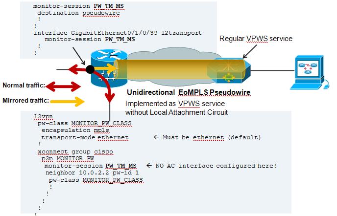
For PW span to work, you need to define a local monitor session with a destination pseudo wire. You apply that span session to the interface of interest and define an xconnect group that also leverages that span session as one of the pw ends.


On the remote side where the PW terminates, you just configure regular VPWS.

Here an example:
 

pw-span.JPG


On the Local Side, besides my Span configuration, there is also a local cross connect between the interested session we want to span over the PW


l2vpn

xconnect group TEST
  p2p TEST
   interface GigabitEthernet0/1/0/39

   ! port 39 is the port where we apply the span on.
   interface GigabitEthernet0/1/0/20.100
  ! this is just a random AC to have traffic flowing between the spanned port.
!


AC configuration:

interface GigabitEthernet0/1/0/20.100 l2transport
encapsulation dot1q 100
rewrite ingress tag pop 1 symmetric
! the tag is popped because the other XCON end is a plain ethernet without vlan. The explanation and use cases of tag popping can be found a related

! Tech note article.


Configuration on the remote side:


Regular VPWS configuration:


RP/0/RSP0/CPU0:A9K-TOP#sh run l2vpn
l2vpn
xconnect group PW-SPAN
  p2p PW-SPAN_1
   interface GigabitEthernet0/0/0/39
   neighbor 2.2.2.2 pw-id 1
   !
  !
!
interface GigabitEthernet0/0/0/39
load-interval 30
transceiver permit pid all
l2transport
!
!


the neighbor in the l2vpn configuration is the LDP neighbor ID
between which the PW is built.


Show on remote side:
RP/0/RSP0/CPU0:A9K-TOP#show l2vpn xcon group PW-SPAN det


Group PW-SPAN, XC PW-SPAN_1, state is up; Interworking none
  AC: GigabitEthernet0/0/0/39, state is up
    Type Ethernet
    MTU 1500; XC ID 0x4000a; interworking none
    Statistics:
      packets: received 0, sent 16570475
      bytes: received 0, sent 994228500

! packets received from the PW are sent out hte Attachment circuit's interface. The analyzer is connected to G0/0/0/39
  PW: neighbor 2.2.2.2, PW ID 1000, state is up ( established )
    PW class not set, XC ID 0x4000a
    Encapsulation MPLS, protocol LDP
    PW type Ethernet, control word disabled, interworking none
    PW backup disable delay 0 sec
    Sequencing not set


      MPLS         Local                          Remote
      ------------ ------------------------------ -----------------------------
      Label        16002                          16027
      Group ID     0xa40                          0x2
      Interface    GigabitEthernet0/0/0/39        PW/TM/MS
      MTU          1500                           1500
      Control word disabled                       disabled
      PW type      Ethernet                       Ethernet
      VCCV CV type 0x2                            0x2
                   (LSP ping verification)        (LSP ping verification)
      VCCV CC type 0x6                            0x6
                   (router alert label)           (router alert label)
                   (TTL expiry)                   (TTL expiry)
      ------------ ------------------------------ -----------------------------
    MIB cpwVcIndex: 4294705162
    Create time: 04/04/2011 14:36:42 (00:20:07 ago)
    Last time status changed: 04/04/2011 14:36:42 (00:20:07 ago)
    Statistics:
      packets: received 16570475, sent 0
      bytes: received 994228500, sent 0

! Packets received on the Pseudo Wire from the SPAN port


NOTE: Pseudo Wire counters on the span side are not incrementing.That is the XCON group "cisco" in this picture config example.

This is intentional. You can review the SPANNING also with this command:


RP/0/RSP1/CPU0:A9K-BOTTOM#sh monitor-session counters

Monitor-session PW_TM_MS
  GigabitEthernet0/1/0/39
    Rx replicated: 58488205 packets, 3743245120 octets
    Tx replicated: 58488206 packets, 3743245184 octets
    Non-replicated: 0 packets, 0 octets


R-SPAN configuration:

R-SPAN is natively support with the capability of ASR9000 to do vlan imposition:


monitor-session MS2

destination interface gig0/2/0/19.10

!

interface gig0/2/0/12.10 l2transport

encapsulation dot1q 10 <<< Monitoring vlan 10 traffic

monitor-session MS2

!

interface gig0/2/0/19.10 l2transport (*)

encapsulation dot1q 100 <<< VLAN 100 will get imposed.

!


(*) Monitor destination could be any supported destination interface regardless of monitor source


Related Information

n/a


Xander Thuijs, CCIE #6775

Sr. Tech Lead ASR9000


https://community.cisco.com/t5/service-providers-documents/asr9000-xr-how-to-use-port-spanning-or-port-mirroring/ta-p/3108031

Wednesday, February 19, 2020

Cisco IOS SPAN and RSPAN

Cisco Catalyst Switches have a feature called SPAN (Switch Port Analyzer) that lets you copy all traffic from a source port or source VLAN to a destination interface. This is very useful for a number of reasons:
  • If you want to use wireshark to capture traffic from an interface that is connected to a workstation, server, phone or anything else you want to sniff.
  • Redirect all traffic from a VLAN to an IDS / IPS.
  • Redirect all VoIP calls from a VLAN so you can record the calls.
The source can be an interface or a VLAN, the destination is an interface. You can choose if you want to forward transmitted, received or both directions to the destination interface.
Cisco SPAN Example
When you use a destination interface on the same switch as your switch we call it SPAN, when the destination is a remote interface on another switch we call it RSPAN (Remote SPAN).  When using RSPAN you need to use a VLAN for your RSPAN traffic so that traffic can travel from the source switch to the destination switch.
cisco switch rspan example
When you use RSPAN you need to use a VLAN that carries the traffic that you are copying. In the picture above you see SW1 which will copy the traffic from the computer onto a “RSPAN VLAN”. SW2 doesn’t do anything with it while SW3 receives the traffic and forwards it to a computer that has wireshark running. Make sure the trunks between the switches allow the RSPAN VLAN.
SPAN and RSPAN are great but there are a couple of things you need to keep in mind…

Restrictions

Both SPAN and RSPAN have some restrictions, I’ll give you an overview of the most important ones:
  • The source interface can be anything…switchport, routed port, access port, trunk port, etherchannel, etc.
  • When you configure a trunk as the source interface it will copy traffic from all VLANs, however there is an option to filter this.
  • You can use multiple source interfaces or multiple VLANs, but you can’t mix interfaces and VLANs.
  • It’s very simple to overload an interface. When you select an entire VLAN as the source and use a 100Mbit destination interface…it might be too much.
  • When you configure a destination port you will “lose” its configuration. By default, the destination interface will only be used to forward SPAN traffic to. However, it can be configured to permit incoming traffic from a device that is connected to the destination interface.
  • Layer 2 frames like CDP, VTP, DTP and spanning-tree BPDUs are not copied by default but you can tell SPAN/RSPAN to copy them anyway.
This should give you an idea of what SPAN / RSPAN are capable of. The configuration is pretty straight-forward so let me give you some examples…

SPAN Configuration

Let’s start with a simple configuration. I will use the example I showed you earlier:
Cisco SPAN Example
Switch(config)#monitor session 1 source interface fa0/1
Switch(config)#monitor session 1 destination interface fa0/2
You can verify the configuration like this:
Switch#show monitor session 1
Session 1
---------
Type                   : Local Session
Source Ports           :
    Both               : Fa0/1
Destination Ports      : Fa0/2
    Encapsulation      : Native
          Ingress      : Disabled
As you can see, by default it will copy traffic that is transmitted and received (both) to the destination port. If you only want the capture the traffic going in one direction you have to specify it like this:
Switch(config)#monitor session 1 source interface fa0/1 ?
  ,     Specify another range of interfaces
  -     Specify a range of interfaces
  both  Monitor received and transmitted traffic
  rx    Monitor received traffic only
  tx    Monitor transmitted traffic only
Just add rx or tx and you are ready to go. If interface FastEthernet 0/1 were a trunk you could add a filter to select the VLANs you want to forward:
Switch(config)#monitor session 1 filter vlan 1 - 100
This filter above will only forward VLAN 1 – 100 to the destination. If you don’t want to use an interface as the source but a VLAN, you can do it like this:
Switch(config)#monitor session 2 source vlan 1
Switch(config)#monitor session 2 destination interface fa0/3
I am unable to use session 1 for this because I am already using source interfaces for that session. It’s also impossible to use the same destination interface for another session. This is why I created another session number and picked FastEthernet 0/3 as a destination.
hostname Switch
!
monitor session 1 source interface Fa0/1
monitor session 1 destination interface Fa0/2
monitor session 2 source vlan 1
monitor session 2 destination interface Fa0/3
end
So far so good? Let’s look at RSPAN!

RSPAN Configuration

To demonstrate RSPAN I will use a topology with two switches:
cisco rspan sw1 sw2
The idea is to forward traffic from FastEthernet 0/1 on SW1 to FastEthernet 0/1 on SW2. There are a couple of things we have to configure here:
SW1(config)#vlan 100
SW1(config-vlan)#remote-span
SW2(config)#vlan 100
SW2(config-vlan)#remote-span
First we need to create the VLAN and tell the switches that it’s a RSPAN vlan. This is something that is easily forgotten. Secondly we will configure the link between the two switches as a trunk:
SW1(config)#interface fastEthernet 0/24
SW1(config-if)#switchport trunk encapsulation dot1q
SW1(config-if)#switchport mode trunk
SW2(config)#interface fastEthernet 0/24
SW2(config-if)#switchport trunk encapsulation dot1q
SW2(config-if)#switchport mode trunk
Now we can configure RSPAN:
SW1(config)#monitor session 1 source interface fastEthernet 0/1
SW1(config)#monitor session 1 destination remote vlan 100
This selects FastEthernet 0/1 as the source and VLAN 100 as the destination…
SW2(config)#monitor session 1 source remote vlan 100
SW2(config)#monitor session 1 destination interface fastEthernet 0/1
And on SW2, we select VLAN 100 as the source and FastEthernet 0/1 as its destination. Here’s the output of the show monitor session command:
SW1#show monitor session 1
Session 1
---------
Type                   : Remote Source Session
Source Ports           :
    Both               : Fa0/1
Dest RSPAN VLAN        : 100
SW2#show monitor session 1
Session 1
---------
Type                   : Remote Destination Session
Source RSPAN VLAN      : 100
Destination Ports      : Fa0/1
    Encapsulation      : Native
          Ingress      : Disabled
That’s all there is to it.
hostname SW1
!
vlan 100
 remote-span
!
interface FastEthernet0/24
 switchport trunk encapsulation dot1q
 switchport mode trunk
!
monitor session 1 source interface Fa0/1
monitor session 1 destination remote vlan 100
end
hostname SW2
!
vlan 100
 remote-span
!
interface FastEthernet0/24
 switchport trunk encapsulation dot1q
 switchport mode trunk
!
monitor session 1 source remote vlan 100
monitor session 1 destination interface fastEthernet 0/1
end
I hope these examples have been helpful to you!