LDP is a protocol that automatically generates and exchanges labels between routers. Each router will locally generate labels for its prefixes and will then advertise the label values to its neighbors.
It’s a standard, based on Cisco’s proprietary TDP (Tag Distribution Protocol). It’s pretty much the same story as 802.1Q/ISL or PaGP/LACP. Cisco created a protocol and a standard was created later. Nowadays almost everyone uses LDP instead of TDP.
Like many other protocols, LDP first establishes a neighbor adjacency before it exchanges label information. It works a bit different than most protocols though…
First we send UDP multicast hello packets to discover other neighbors. Once two routers decide to become neighbors, they build the neighbor adjacency using a TCP connection. This connection is then used for the exchange of label information. Normally a loopback interface is used for the neighbor adjacency. Here’s an example:

The two routers above will send multicast hello packets on their FastEthernet interfaces. Within this hello packet, they will advertise a transport IP address. This IP address is then used to establish the TCP connection between the two routers. Here’s what the hello packet looks like in wireshark:

In the capture above you can see a couple of interesting things:
- The hello packets are sent to multicast address 224.0.0.2 using source/destination UDP port 646.
- Each router has a unique ID called the LSR (Label Switch Router) ID. This is similar to how most protocols select an ID, by default it will select the highest IP address on a loopback interface. If you don’t have any loopback interfaces then we will use the highest IP address on a physical interface.
- At the bottom you find the transport address. This is what we use to build the actual TCP connection. Like the LSR ID, the router selected the IP address on the loopback interface as the transport address.
Make sure that the IP address that LDP has selected for the transport address is advertised in your routing protocol. Otherwise your routers will be able to hear each others hello packets but they can’t form a neighbor adjacency since the transport address(es) are unreachable.
This is different compared to how routing protocols like OSPF or EIGRP form neighbor adjacencies. For example, when you run OSPF then your routers will form neighbor adjacencies on all interfaces that run OSPF:

LDP will only form a single neighbor adjacency, no matter how many interfaces you have in between your routers:

LDP is a bit similar to BGP when you use the loopback interfaces for the neighbor adjacency. When we use BGP we have to use the update-source command to select the source, LDP does it automatically.
So once our LDP routers have become neighbors, how do we exchange label information? To explain this, let’s do a quick review of how normal routing uses the RIB and FIB. If you have no idea what these two are then I recommend you to read my CEF tutorial first before you continue.

With normal routing, we use routing protocols like EIGRP, OSPF or BGP to learn prefixes from other routers. These are all stored in the RIB (Routing Information Base), this is your routing table.
The information in the RIB is used to build the FIB (Forwarding Information Base) which is what we use for actual forwarding of IP packet. These tables are all used for IP packets but for MPLS we use something else:

When we use LDP on Cisco IOS, we locally generate a label for each prefix that we can find in the RIB, except for BGP prefixes. This information is then added to the LIB (Label Information Base).
The information in the LIB is used to build the LFIB (Label Forwarding Information Base). When the router has to forward a packet with a MPLS label on it, it will use the LFIB for forwarding decisions.
The LIB is similar to the RIB but it’s used to store labels for prefixes. The LFIB is similar to the FIB, it’s used for actual forwarding of MPLS packets.
Two routers that have formed a LDP neighbor adjacency will exchange the label information in their LIBs to tell each other what label values to use for different prefixes.
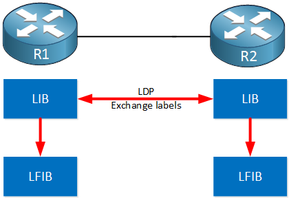
All routers running LDP will now know what label values to use when they switch a MPLS packet to their neighbor.
Now you have an idea what LDP is about, let’s take a look at it in action. I will also show you the different tables that I just described.
Configuration
I will use the following three routers to demonstrate LDP:
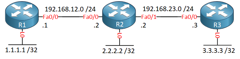
Each router has a loopback interface that we will use for the LDP neighbor adjacency. LDP will select the IP addresses on the loopback interfaces as the LSR IDs and the transport addresses. We also need the information in the RIB to build the LIB so I’ll configure OSPF to advertise all prefixes.
OSPF Configuration
Let’s advertise all interfaces:
R1(config)#router ospf 1
R1(config-router)#network 192.168.12.0 0.0.0.255 area 0
R1(config-router)#network 1.1.1.1 0.0.0.0 area 0R2(config)#router ospf 1
R2(config-router)#network 192.168.12.0 0.0.0.255 area 0
R2(config-router)#network 192.168.23.0 0.0.0.255 area 0
R2(config-router)#network 2.2.2.2 0.0.0.0 area 0R3(config)#router ospf 1
R3(config-router)#network 192.168.23.0 0.0.0.255 area 0
R3(config-router)#network 3.3.3.3 0.0.0.0 area 0
That’s all we need.
LDP Configuration
There are two ways to configure LDP:
- On the interface level with the mpls ip command.
- Globally under the OSPF process with the mpls ldp autoconfig command.
It doesn’t matter much which one you pick, by default LDP will create a label for each prefix. I’ll enable it on the interfaces this time:
R1(config)#interface FastEthernet 0/0
R1(config-if)#mpls ipR2(config)#interface FastEthernet 0/0
R2(config-if)#mpls ipR2(config)#interface FastEthernet 0/1
R2(config-if)#mpls ipR3(config)#interface FastEthernet 0/0
R3(config-if)#mpls ip
After a few seconds you will see a message on the consoles telling you that the neighbor is up:
R1#
%LDP-5-NBRCHG: LDP Neighbor 2.2.2.2:0 (1) is UP
That’s all you have to do to enable LDP. Let’s verify our work!
Verification
The messages on the console(s) revealed to us that we have a neighbor adjacency but it still might be useful to check some things yourself.
LDP Neighbor Adjacency
First let’s check if LDP is enabled on the interface:
R1#show mpls interfaces
Interface              IP            Tunnel   BGP Static Operational
FastEthernet0/0 Yes (ldp) No No No YesR2#show mpls interfaces
Interface IP Tunnel BGP Static Operational
FastEthernet0/0 Yes (ldp) No No No Yes
FastEthernet0/1 Yes (ldp) No No No YesR3#show mpls interfaces
Interface IP Tunnel BGP Static Operational
FastEthernet0/0 Yes (ldp) No No No Yes
The show mpls interfaces command is a quick way to see if LDP is enabled or not. It tells us what interfaces are enabled and if they are operational or not. The next thing to check is if we have LDP neighbors or not:
R2#show mpls ldp neighbor
    Peer LDP Ident: 1.1.1.1:0; Local LDP Ident 2.2.2.2:0
        TCP connection: 1.1.1.1.646 - 2.2.2.2.36200
        State: Oper; Msgs sent/rcvd: 8/7; Downstream
        Up time: 00:00:32
        LDP discovery sources:
          FastEthernet0/0, Src IP addr: 192.168.12.1
        Addresses bound to peer LDP Ident:
          192.168.12.1    1.1.1.1
    Peer LDP Ident: 3.3.3.3:0; Local LDP Ident 2.2.2.2:0
        TCP connection: 3.3.3.3.13500 - 2.2.2.2.646
        State: Oper; Msgs sent/rcvd: 8/8; Downstream
        Up time: 00:00:12
        LDP discovery sources:
          FastEthernet0/1, Src IP addr: 192.168.23.3
        Addresses bound to peer LDP Ident:
          192.168.23.3    3.3.3.3
Akove you see the output of R2. Here’s what you see:
- R2 and R3 have become neighbors:
- R2 uses 2.2.2.2 as its LSR ID, R3 uses 3.3.3.3 as the LSR ID.
- R2 and R3 have formed a TCP connection using 2.2.2.2 and 3.3.3.3 as the transport addresses.
- Discovery (hello packets) was done using the FastEthernet0/1 interface.
- R1 and R2 have become neighbors:
- R2 uses 2.2.2.2 as its LSR ID, R1 uses 1.1.1.1 as the LSR ID.
- R1 and R2 have formed a TCP connection using 2.2.2.2 and 1.1.1.1 as the transport addresses.
- Discovery (hello packets) was done using the FastEthernet0/0 interface.
Now we have confirmed that we have LDP neighbors, let’s look at the labels.
LDP Control Plane
When you use LDP, all routers will start assigning labels with label value 16. This might be a bit annoying if you are new to MPLS as some routers will use the same label value. To make it easier to read the different tables I will configure each router to use different label values. Here’s how to do this:
R1(config)#mpls label range 100 199R2(config)#mpls label range 200 299R3(config)#mpls label range 300 399
When you use this command you will have to reload the routers, clearing the neighbor adjacency is not enough. Let’s take a look at some labels. Since the LIB is built with information from the RIB, we will start with the routing table. Here’s R1:
R1#show ip route

      1.0.0.0/32 is subnetted, 1 subnets
C        1.1.1.1 is directly connected, Loopback0
      2.0.0.0/32 is subnetted, 1 subnets
O        2.2.2.2 [110/2] via 192.168.12.2, 00:36:02, FastEthernet0/0
      3.0.0.0/32 is subnetted, 1 subnets
O        3.3.3.3 [110/3] via 192.168.12.2, 00:36:02, FastEthernet0/0
      192.168.12.0/24 is variably subnetted, 2 subnets, 2 masks
C        192.168.12.0/24 is directly connected, FastEthernet0/0
L        192.168.12.1/32 is directly connected, FastEthernet0/0
O     192.168.23.0/24 [110/2] via 192.168.12.2, 00:36:02, FastEthernet0/0
Above you can see the prefixes in the routing table. Here’s what the LIB looks like:
R1#show mpls ldp bindings
  lib entry: 1.1.1.1/32, rev 4
 local binding:  label: imp-null
 remote binding: lsr: 2.2.2.2:0, label: 200
  lib entry: 2.2.2.2/32, rev 6
 local binding:  label: 100
 remote binding: lsr: 2.2.2.2:0, label: imp-null
  lib entry: 3.3.3.3/32, rev 10
 local binding:  label: 102
 remote binding: lsr: 2.2.2.2:0, label: 201
  lib entry: 192.168.12.0/24, rev 2
 local binding:  label: imp-null
 remote binding: lsr: 2.2.2.2:0, label: imp-null
  lib entry: 192.168.23.0/24, rev 8
 local binding:  label: 101
 remote binding: lsr: 2.2.2.2:0, label: imp-null
Above you can see the LIB of R1. Let’s walk through some of the things we see here:
- The first entry is for 1.1.1.1/32, the loopback interface of R1. This router doesn’t generate a label value for this entry since it’s directly connected. You can see however that R2 has advertised to R1 that it uses label value 200 for this prefix.
- The second entry is for 2.2.2.2/32. R1 has chosen label value 100 for this entry, we can also see that R2 doesn’t use a label for this prefix. This makes sense since it’s directly connected for R2.
- The third entry for 3.3.3.3/32 has a local label value of 102. R2 is using label value 201 for this entry.
- The fourth entry is 192.168.12.0/24. We don’t use a label for this entry since it’s directly connected. R2 also doesn’t use a label value since it’s directly connected there as well.
- The fifth entry is for 192.168.23.0/24, R1 uses label value 101 for this one.
Now let’s take a look at the LFIB, that’s what we will actually use when we forward MPLS packets:
R1#show mpls forwarding-table
Local      Outgoing   Prefix           Bytes Label   Outgoing   Next Hop
Label      Label      or Tunnel Id     Switched      interface
100        Pop Label  2.2.2.2/32       0             Fa0/0      192.168.12.2
101        Pop Label  192.168.23.0/24  0             Fa0/0      192.168.12.2
102        201        3.3.3.3/32       0             Fa0/0      192.168.12.2
The LFIB is much smaller, keep in mind that this is similar to the CEF table that we use for IP forwarding. There is no entry for 1.1.1.1 /32 or 192.168.12.0 /24 here since we don’t have a label for these prefixes. When we want to reach 3.3.3.3 /32 then we will add label value 201 to the MPLS header before we send it to R2.
When R1 receives something for 2.2.2.2/32 or 192.168.23.0/24 then we will “pop the label” before we forward it to R2. This is called penultimate hop popping. I’ll explain this in more detail in another post, it’s done to save R2 some time by already removing the MPLS header.
Let me also show you the RIB, LIB and LFIB of R2 and R3:
R2#show ip route

      1.0.0.0/32 is subnetted, 1 subnets
O        1.1.1.1 [110/2] via 192.168.12.1, 00:44:37, FastEthernet0/0
      2.0.0.0/32 is subnetted, 1 subnets
C        2.2.2.2 is directly connected, Loopback0
      3.0.0.0/32 is subnetted, 1 subnets
O        3.3.3.3 [110/2] via 192.168.23.3, 02:55:40, FastEthernet0/1
      192.168.12.0/24 is variably subnetted, 2 subnets, 2 masks
C        192.168.12.0/24 is directly connected, FastEthernet0/0
L        192.168.12.2/32 is directly connected, FastEthernet0/0
      192.168.23.0/24 is variably subnetted, 2 subnets, 2 masks
C        192.168.23.0/24 is directly connected, FastEthernet0/1
L 192.168.23.2/32 is directly connected, FastEthernet0/1R2#show mpls ldp bindings
lib entry: 1.1.1.1/32, rev 8
local binding: label: 200
remote binding: lsr: 3.3.3.3:0, label: 301
remote binding: lsr: 1.1.1.1:0, label: imp-null
lib entry: 2.2.2.2/32, rev 6
local binding: label: imp-null
remote binding: lsr: 3.3.3.3:0, label: 300
remote binding: lsr: 1.1.1.1:0, label: 100
lib entry: 3.3.3.3/32, rev 10
local binding: label: 201
remote binding: lsr: 3.3.3.3:0, label: imp-null
remote binding: lsr: 1.1.1.1:0, label: 102
lib entry: 192.168.12.0/24, rev 2
local binding: label: imp-null
remote binding: lsr: 3.3.3.3:0, label: 302
remote binding: lsr: 1.1.1.1:0, label: imp-null
lib entry: 192.168.23.0/24, rev 4
local binding: label: imp-null
remote binding: lsr: 3.3.3.3:0, label: imp-null
remote binding: lsr: 1.1.1.1:0, label: 101R2#show mpls forwarding-table
Local Outgoing Prefix Bytes Label Outgoing Next Hop
Label Label or Tunnel Id Switched interface
200 Pop Label 1.1.1.1/32 0 Fa0/0 192.168.12.1
201 Pop Label 3.3.3.3/32 126 Fa0/1 192.168.23.3
And here’s R3:
R3#show ip route

      1.0.0.0/32 is subnetted, 1 subnets
O        1.1.1.1 [110/3] via 192.168.23.2, 00:45:50, FastEthernet0/0
      2.0.0.0/32 is subnetted, 1 subnets
O        2.2.2.2 [110/2] via 192.168.23.2, 02:57:05, FastEthernet0/0
      3.0.0.0/32 is subnetted, 1 subnets
C        3.3.3.3 is directly connected, Loopback0
O     192.168.12.0/24 [110/2] via 192.168.23.2, 00:45:50, FastEthernet0/0
      192.168.23.0/24 is variably subnetted, 2 subnets, 2 masks
C        192.168.23.0/24 is directly connected, FastEthernet0/0
L 192.168.23.3/32 is directly connected, FastEthernet0/0R3#show mpls ldp bindings
lib entry: 1.1.1.1/32, rev 10
local binding: label: 301
remote binding: lsr: 2.2.2.2:0, label: 200
lib entry: 2.2.2.2/32, rev 8
local binding: label: 300
remote binding: lsr: 2.2.2.2:0, label: imp-null
lib entry: 3.3.3.3/32, rev 6
local binding: label: imp-null
remote binding: lsr: 2.2.2.2:0, label: 201
lib entry: 192.168.12.0/24, rev 12
local binding: label: 302
remote binding: lsr: 2.2.2.2:0, label: imp-null
lib entry: 192.168.23.0/24, rev 2
local binding: label: imp-null
remote binding: lsr: 2.2.2.2:0, label: imp-null
R3#show mpls forwarding-table
Local      Outgoing   Prefix           Bytes Label   Outgoing   Next Hop
Label      Label      or Tunnel Id     Switched      interface
300        Pop Label  2.2.2.2/32       0             Fa0/0      192.168.23.2
301        200        1.1.1.1/32       0             Fa0/0      192.168.23.2
302        Pop Label  192.168.12.0/24  0             Fa0/0      192.168.23.2
LDP Data Plane
All these tables allow us to check the control plane but what about the data plane? We can use a quick traceroute to see if we are using label switching:
R1#traceroute 3.3.3.3 source 1.1.1.1
Type escape sequence to abort.
Tracing the route to 3.3.3.3
VRF info: (vrf in name/id, vrf out name/id)
  1 192.168.12.2 [MPLS: Label 201 Exp 0] 0 msec 0 msec 4 msec
  2 192.168.23.3 0 msec 0 msec *
When you use traceroute on your MPLS devices then you can see the labels that we use. The path that we use here is called the LSP (Label Switched Path).
Conclusion
You have now learned how LDP uses multicast to send hello packets to discover other LDP routers. You have seen how we establish a neighbor adjacency using a TCP connection and the transport addresses in the hello packet.
We also discussed the different tables that we use for IP and MPLS forwarding. Last but not least, you have seen some of the labels in action. I can recommend you to boot up some routers yourself, enable LDP and then take a look at it yourself.
In the next lessons we will look at VRFs and MPLS VPN. If you have any questions, feel free to leave a comment!
No comments:
Post a Comment