EIGRP Authentication can only be enabled on the interface level and it’s impossible to configure this per neighbor on a multi-access network. What can we do if we face the following requirements in a CCIE lab exam?
- Enable EIGRP authentication between R1 and R2 using key “R1-R2”.
- Enable EIGRP authentication between R1 and R3 using key “R1-R3”.
- You are not allowed to use sub-interfaces or configure additional subnets.
- Don’t change the EIGRP AS Number.
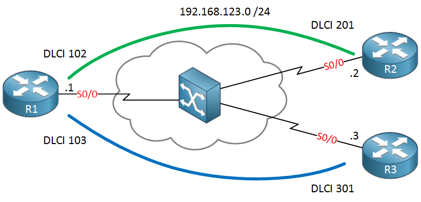
This is a tricky solution but fortunately there is a nice workaround for this. In this tutorial I’ll show you how the problem and how to fix it. The network that we will use is a simple hub and spoke frame-relay topology. R1 is our hub router and R2 / R3 are spoke routers:
 We’ll start by configuring frame-relay, adding some IP addresses and enable EIGRP:
R1(config)#interface serial0/0
R1(config-if)#encapsulation frame-relay
R1(config-if)#no shutdown
R1(config-if)#ip address 192.168.123.1 255.255.255.0R2(config)#interface serial0/0
R2(config-if)#encapsulation frame-relay
R2(config-if)#no shutdown
R2(config-if)#ip address 192.168.123.2 255.255.255.0R3(config)#interface serial0/0
R3(config-if)#encapsulation frame-relay
R3(config-if)#no shutdown
R3(config-if)#ip address 192.168.123.3 255.255.255.0
This allows reachability between the Hub and spoke routers. Let’s enable EIGRP:
R1, R2 & R3:
router eigrp 123
no auto-summary
network 192.168.123.0
Nothing special so far, I just want to make sure the routers become neighbors. Let’s make sure R1 has two neighbors:
R1#show ip eigrp neighbors
IP-EIGRP neighbors for process 123
H   Address                 Interface       Hold Uptime   SRTT   RTO  Q  Seq
                                            (sec)         (ms)       Cnt Num
1   192.168.123.2           Se0/0            143 00:00:38 1604  5000  0  3
0   192.168.123.3           Se0/0            143 00:00:38   23   200  0  3
Perfect, we have some neighbors. Our next move is to configure some key chains. One for R1-R2 and another one for R1-R3:
R1(config)#key chain R1-R2
R1(config-keychain)#key 1
R1(config-keychain-key)#key-string R1-R2R1(config)#key chain R1-R3
R1(config-keychain)#key 1
R1(config-keychain-key)#key-string R1-R3
Creating key chains is no problem, now we need to activate it on the interface:
R1(config-if)#ip authentication key-chain eigrp 123 R1-R2 ?
  <cr>
Here’s our problem…we can only configure a single key chain on an interface and there’s no way to specify the neighbor or something. There’s no way to get around this…maybe you are thinking about playing with the key IDs, perhaps using key 1 for R2 and key 2 for R3 or something. This sounds plausible, but there’s no way to tell EIGRP which key to use for a certain neighbor.
There is a trick however to make this work and without breaking our requirements. We can use virtual-templates to get the job done.
For each PVC we will create a virtual-template and we will attach the key chain to the corresponding virtual-template. This allows us to use different keys between neighbors.
Let’s start with R1 and create the virtual templates:
R1(config)#interface virtual-template 12
R1(config-if)#ip address 192.168.123.1 255.255.255.0
R1(config-if)#ip authentication mode eigrp 123 md5
R1(config-if)#ip authentication key-chain eigrp 123 R1-R2

R1(config)#interface virtual-template 13
R1(config-if)#ip address 192.168.123.1 255.255.255.0
R1(config-if)#ip authentication mode eigrp 123 md5
R1(config-if)#ip authentication key-chain eigrp 123 R1-R3
Virtual-template 12 is for the PVC between R1-R2 and virtual-template 13 is for the PVC between R1-R3. As you can see I attached the different key chains to the virtual templates. Also note that I used the same IP address on both virtual templates.
Let’s enable those virtual templates on the interface now:
R1(config)#interface serial 0/0
R1(config-if)#no ip address 192.168.123.1 255.255.255.0
R1(config-if)#frame-relay interface-dlci 102 ppp Virtual-Template 12
R1(config-if)#frame-relay interface-dlci 103 ppp Virtual-Template 13
The only way to attach the virtual template to the interface / PVC is by using PPPoFR. This is no problem but it means we’ll have to configure the spokes for PPPoFR as well. Here’s R2:
R2(config)#key chain R1-R2
R2(config-keychain)#key 1
R2(config-keychain-key)#key-string R1-R2

R2(config)#interface virtual-template 12
R2(config-if)#ip address 192.168.123.2 255.255.255.0
R2(config-if)#ip authentication mode eigrp 123 md5
R2(config-if)#ip authentication key-chain eigrp 123 R1-R2

R2(config)#interface serial 0/0
R2(config-if)#no ip address 192.168.123.2 255.255.255.0
R2(config-if)#frame-relay interface-dlci 201 ppp Virtual-Template 12
And we will do the same thing for R3:
R3(config)#key chain R1-R3
R3(config-keychain)#key 1
R3(config-keychain-key)#key-string R1-R3

R3(config)#interface virtual-template 13
R3(config-if)#ip address 192.168.123.3 255.255.255.0
R3(config-if)#ip authentication mode eigrp 123 md5
R3(config-if)#ip authentication key-chain eigrp 123 R1-R3

R3(config-if)#interface serial 0/0
R3(config-if)#no ip address 192.168.123.3 255.255.255.0
R3(config-if)#frame-relay interface-dlci 301 ppp Virtual-Template 13
All routers are now configured for PPPoFR and we have different keys for each PVC. Let’s see if everything is working:
R1#ping 192.168.123.2

Type escape sequence to abort.
Sending 5, 100-byte ICMP Echos to 192.168.123.2, timeout is 2 seconds:
!!!!!
Success rate is 100 percent (5/5), round-trip min/avg/max = 1/6/16 msR1#ping 192.168.123.3
Type escape sequence to abort.
Sending 5, 100-byte ICMP Echos to 192.168.123.3, timeout is 2 seconds:
!!!!!
Success rate is 100 percent (5/5), round-trip min/avg/max = 1/9/24 ms
Pings are working…do we have an EIGRP neighbor adjacency?
R1#show ip eigrp neighbors
IP-EIGRP neighbors for process 123
H   Address                 Interface       Hold Uptime   SRTT   RTO  Q  Seq
                                            (sec)         (ms)       Cnt Num
1   192.168.123.3           Vi3               13 00:05:09   32   200  0  7
0   192.168.123.2           Vi2               13 00:07:47   33   200  0  7
R1 shows two EIGRP neighbors, the interface field shows the virtual template interfaces…if you enable a debug you can see that the packets are authenticated:
R1#debug eigrp packets
EIGRP Packets debugging is on
    (UPDATE, REQUEST, QUERY, REPLY, HELLO, IPXSAP, PROBE, ACK, STUB, SIAQUERY, SIAREPLY)
R1#
EIGRP: received packet with MD5 authentication, key id = 1
EIGRP: Received HELLO on Virtual-Access2 nbr 192.168.123.2
EIGRP: received packet with MD5 authentication, key id = 1
EIGRP: Received HELLO on Virtual-Access3 nbr 192.168.123.3
EIGRP packets from both neighbors are authenticated but we are using different key chains…problem solved!
If you enjoyed this tutorial, please share it with your friends and colleagues!
No comments:
Post a Comment