When there are multiple receivers on the network then using multicast traffic sounds like a good idea. It’s more efficient than unicast since we only have to have to send our traffic once, this saves us precious bandwidth. It’s also more efficient than broadcast since only receives that are actually interested in our traffic will receive it.
Routers use PIM (Protocol Independent Multicast) to figure out where to forward multicast traffic but what about switches?
Layer two switches are simple devices. They learn source MAC addresses and insert these in their MAC address tables. When a frame arrives, they check for the destination MAC address, perform a lookup in the MAC address table and then forward the frame. This works very well for unicast traffic but it’s a problem for multicast traffic. Take a look at the example below:
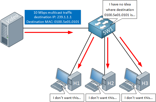
Above we have a video server that is streaming multicast traffic to destination 239.1.1.1, the destination MAC address will be 0100.5e01.0101. When the switch receives this traffic then it will do a lookup for MAC address 0100.5e01.0101. Since this MAC address has never been used as a source, all multicast traffic will be flooded. All hosts will receive our traffic whether they want it or not.
IGMP snooping allows us to constrain our multicast traffic. As the name implies, this is done by listening to IGMP traffic between the router and hosts:
- When the host sends a membership report for a multicast group then the switch adds an entry in the CAM table for the interface that is connected to the host.
- When the host sends a leave group for a multicast group then the switch removes an entry in the CAM table for the interface that is connected to the host.
This sounds simple but there is more to this story.
What do we do when we use IGMP version 1? Our hosts will not send any leave group messages so there’s nothing to snoop. How do we deal with the video server that never joins any multicast groups but only streams traffic to it?
To answer these questions we’ll have to take a closer look at IGMP snooping.
IGMP snooping without L3 aware ASICs
We will start with a simple example. I’ll use the following diagram for this:
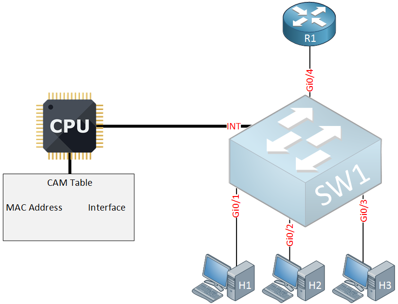
Above we have a multicast enabled router, a switch and three host devices. Our switch has a CPU and a CAM table (mac address table) which is connected to an internal interface that I will call “INT”. We are using a cheap budget switch that is only able to look at layer two Ethernet frames. It does have support for IGMP snooping though. Let’s see what happens when we enable IGMP snooping on this switch:
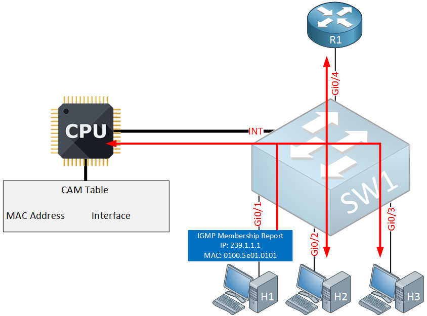
Above you can see that one of our hosts (H1) sends a membership report for multicast group 239.1.1.1 that it wants to join. Our switch has no idea where to forward this to so the first time it will flood it on all interfaces, including the internal interface to the CPU. The CPU will take a closer look at the membership report and will create an entry in the CAM table:
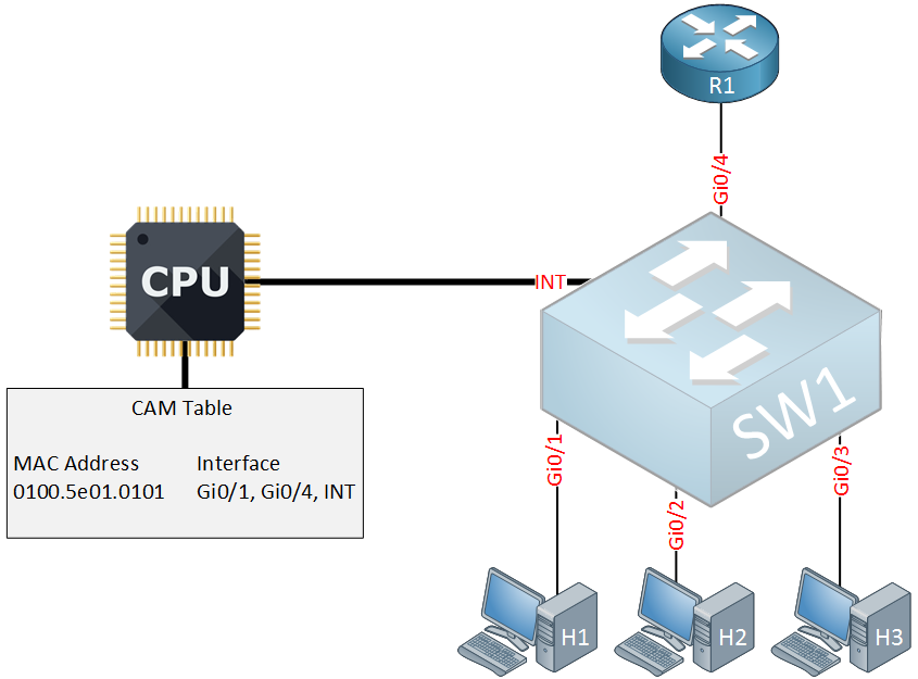
In the CAM table above you can see an entry for MAC address 0100.5e01.0101 which corresponds with multicast group 239.1.1.1. The interfaces that were added are for H1, R1 and the internal interface. Why did the switch add the interface of the router in the CAM table?
Once IGMP snooping is enabled, the switch will detect multicast enabled routers and it does so by listening to the following messages:
- IGMP General Query (0100.5e00.0001)
- OSPF (0100.5e00.0005 and 0100.5e00.0006)
- PIM version 1 and HSRP (0100.5e00.0006)
- PIM version 2 (0100.5e00.000d)
- DVMRP (0100.5e00.0004)
When the switch detects a multicast enabled router then it will add the corresponding entry in the CAM table.
From now on, all multicast traffic that has destination MAC address 0100.5e01.0101 will only be forwarded on interface Gi0/1, Gi0/4 and the internal interface to the CPU.
It sounds like we did a good job constraining our multicast traffic but we still have one problem. Here’s what happens when one of our devices starts streaming multicast traffic:

In the example above we see that R1 is sending 10 Mbps of multicast traffic which is forwarded to H1 and the CPU. Our CPU is unable to process 10 Mbps of traffic so it will choke on it…when this occurs, there’s a couple of things that could occur:
- The switch will start dropping unicast and multicast traffic.
- The CPU might be able to drop exceeding multicast traffic but that could also include IGMP membership reports and IGMP group leave messages.
The issue above is common with cheap switches that support IGMP snooping. It might work with low bandwidth multicast traffic but that’s about it.
IGMP snooping with L3 aware ASICs
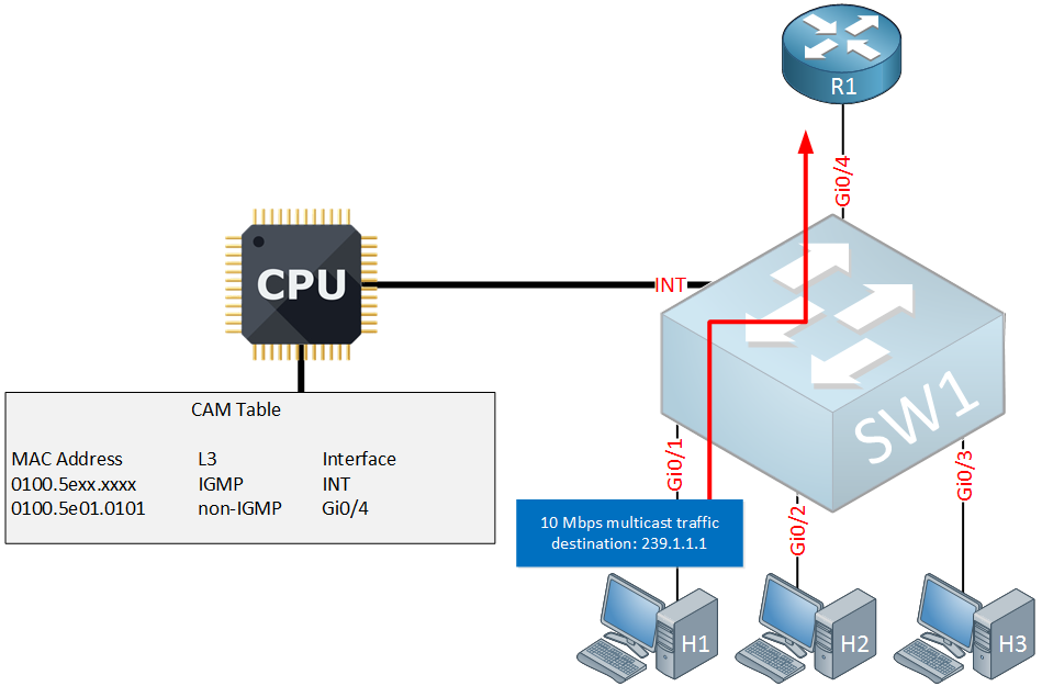
To fix this issue, we need switches with special ASICs that are able to look into the frame and differentiate between IGMP and non-IGMP multicast traffic. Here’s what that would look like:
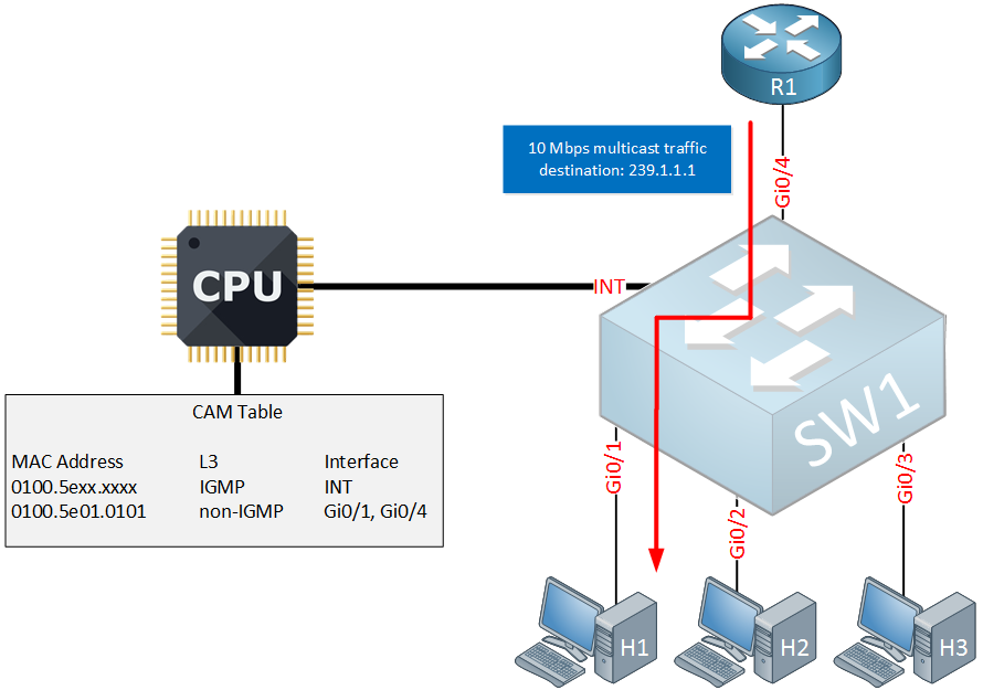
Above you can see the changes that were made to the CAM table:
- The first entry tells the switch to forward all IGMP traffic with destination 0100.5exx.xxx to the internal interface. This allows the CPU to look at the different IGMP messages.
- The second entry tells the switch to forward all non-IGMP traffic with destination 0100.5e01.0101 (group 239.1.1.1) to interface Gi0/1 and Gi0/4.
The switch will now intercept all IGMP messages, they are only sent to the internal interface which puts our switch in total control of all IGMP traffic.
IGMP Group Leave
Let’s continue the story, let’s say that H1 and H2 are listening to multicast group 239.1.1.1. Suddenly, H1 is no longer interested so it will send a leave group message:
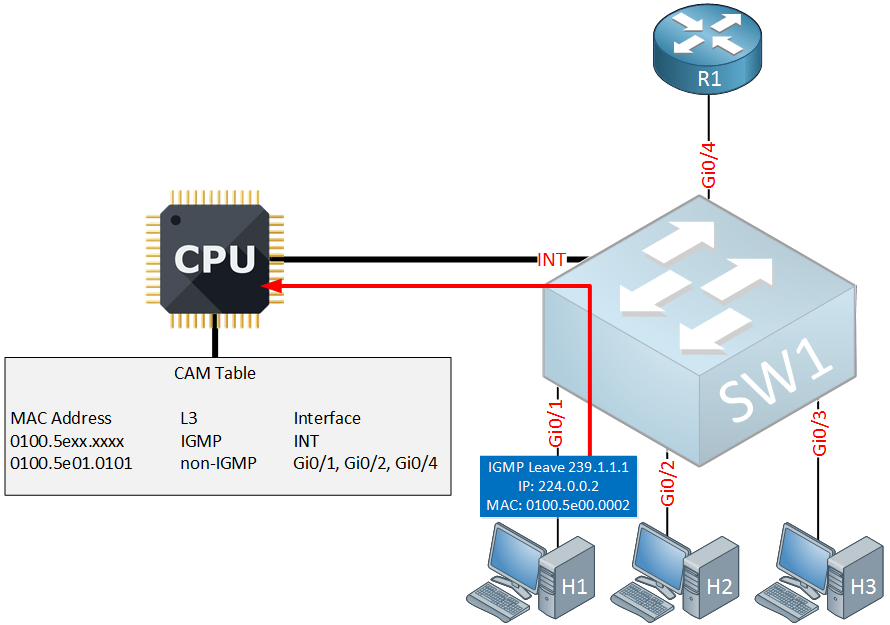
Leave group messages are always sent to multicast group 224.0.0.2 using destination MAC address 0100.5e00.0002. When the switch receives the IGMP leave, it will forward it on the internal interface to the CPU.
In response, the switch will send an IGMP general query on the interface that connects to H1:
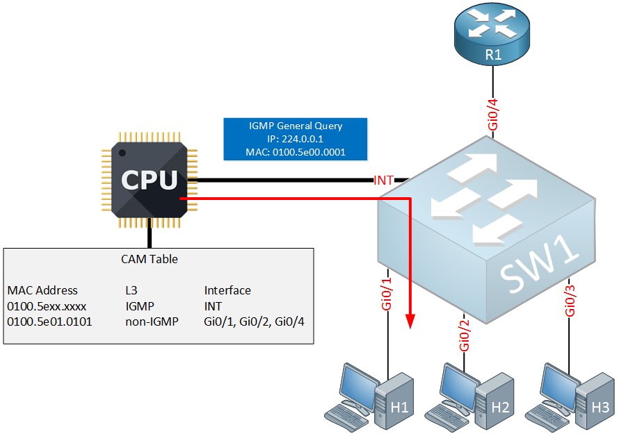
The IGMP general query is only sent on the Gi0/1 interface and we do this to check if there are any other hosts that are interested in multicast group 239.1.1.1 on this interface. There are two possible outcomes:
- If another host was connected to the Gi0/1 interface which was still interested in receiving traffic for 239.1.1.1 then the switch would just get rid of the group leave message, nothing will change.
- When the switch doesn’t receive a membership report then the CPU will remove the Gi0/1 interface from the CAM table. Since we still have a second listener (H2), the switch will not forward the leave group message to the router.
Here’s what the CAM table looks like now:
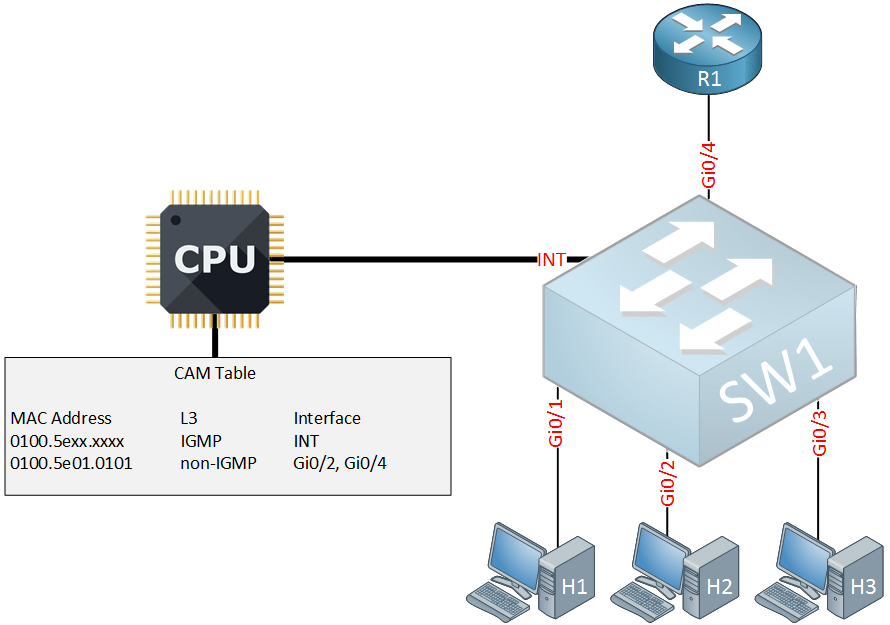
Above you can see that interface Gi0/1 has been removed from the CAM table. No messages have been forwarded to the router.
A few minutes later, H2 decides that it also wants to leave multicast group 239.1.1.1 so it will send an IGMP leave group message:
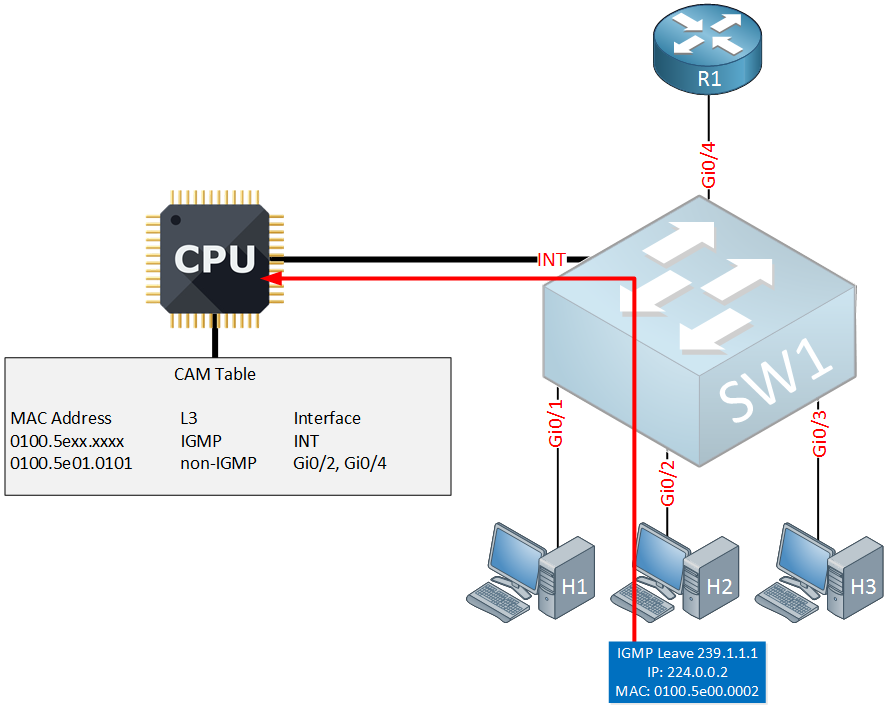
Above you can see the switch receives the IGMP leave group from H2 which is forwarded to the CPU. Here’s what happens next:
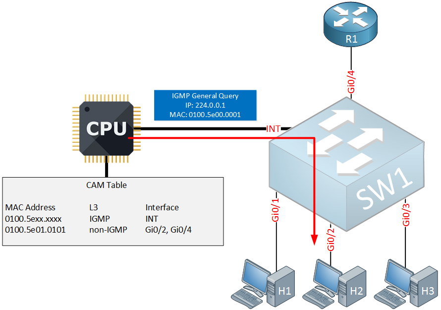
Once again, the switch will send a IGMP general query message on the interface that connects to H2. This time however, we don’t have any listeners left for 239.1.1.1. Here’s what the switch will do now:
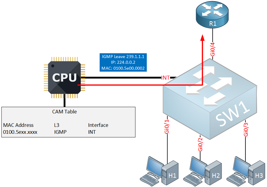
Since there are no listeners left, our switch will now forward the IGMP leave message to the router so that the router can stop forwarding traffic to 239.1.1.1.
Maintaining Groups
Everything we have seen so far works great but there’s one issue. It relies on the IGMP leave group messages that are sent by the listeners, otherwise the switch can’t remove the interfaces from the CAM table. This can become an issue when:
- You use IGMP version 1, it doesn’t have any group leave messages.
- The hosts don’t send IGMP leave messages. Sending group leave messages is not a requirement so it’s possible that some hosts just don’t do it.
To get around this, we can use the general query / report mechanism. Normally the router will periodically send a general query message and the hosts have to respond that they are still interested in receiving multicast traffic for a particular group. Let’s look at an example:
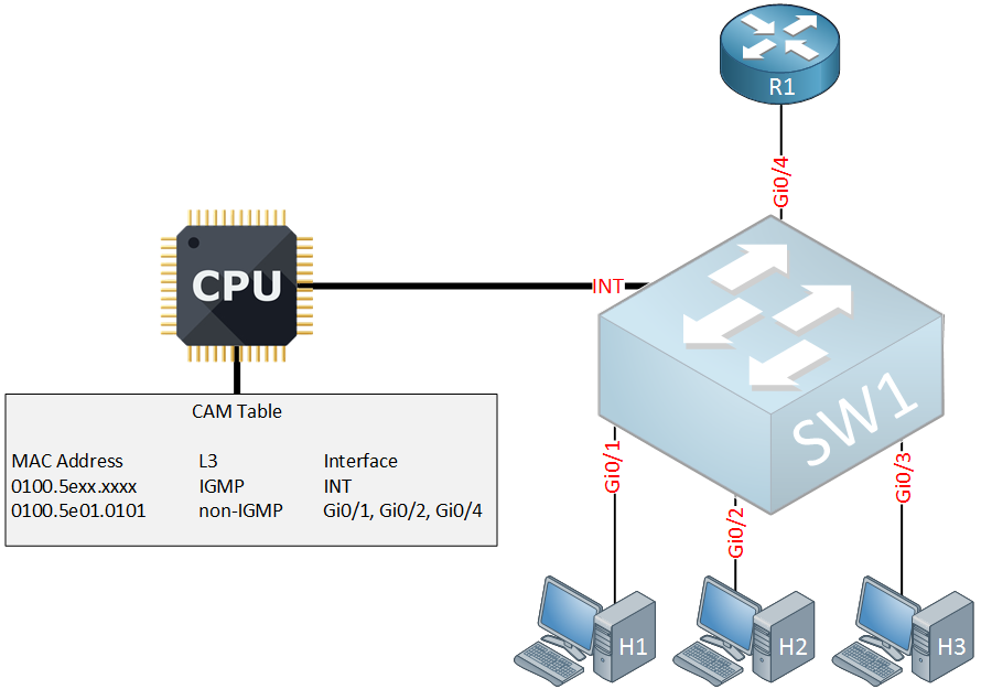
Above we have the same network, currently H1 and H2 are both interested in receiving multicast group 239.1.1.1 which corresponds with MAC address 0100.5e01.0101. Suddenly the router sends its periodically general query message:
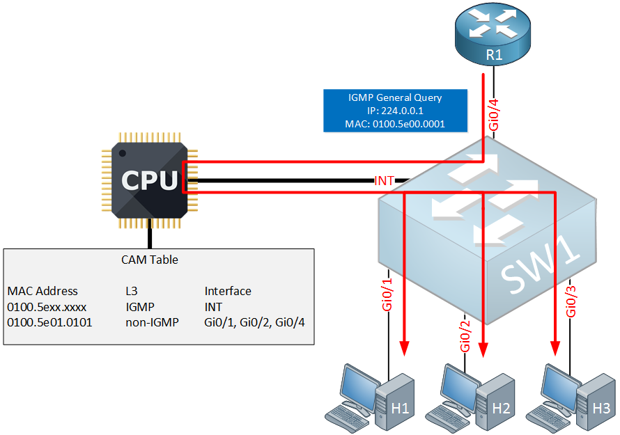
The switch will intercept the IGMP general query and forwards it to the CPU and all other interfaces. Our listeners will then respond to it:
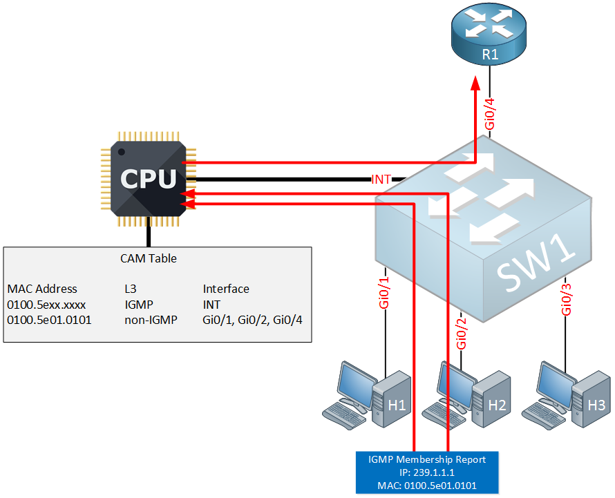
H1 and H2 are still interested so they will respond with a membership report. The switch will intercept these two messages and forwards them to the CPU. One of the two membership reports is then forwarded to the router.
Since the switch intercepts these IGMP membership reports, our hosts don’t hear each others membership reports. This overrules the membership report suppression mechanism which I described in the IGMP version 2 lesson. This is required since the switch has to hear the membership report from all interfaces that need to receive the multicast traffic.
Send only Source
The last problem we have to talk about that IGMP snooping has to tackle is a source that only sends multicast traffic. Take a look at the following picture:
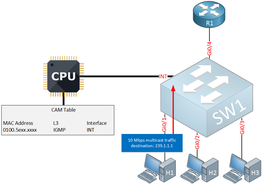
Above we see H1 which is sending traffic to multicast destination 239.1.1.1. It never sent any membership reports so there is nothing in the CAM table. The switch now has a decision to make…where will it forward this traffic to?
The first option is to flood this traffic everywhere:
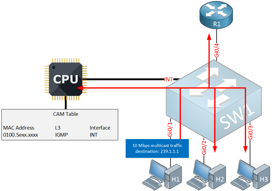
Above you can see that traffic is flooded to all interfaces. This is something you probably encounter on a cheap switch that doesn’t have any L3 aware ASICs.
Any decent switch that does have L3 aware ASICs will probably do something else. One option is to forward the traffic only to the router interface:
Above you can see that the traffic is only forwarded to the router. Nobody is interested in it at the moment but at least it’s a better solution then flooding the traffic everywhere.
Configuration
You now have learned how IGMP snooping works on switches so let’s take a look at the configuration. I’ll use the following topology for this:
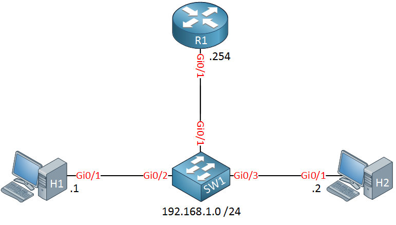
Above we have two hosts, one router and a switch that will use IGMP snooping. Multicast has not been configured yet.
Let’s take a look at the switch:
SW1#show ip igmp snooping
Global IGMP Snooping configuration:
-------------------------------------------
IGMP snooping                : Enabled
IGMPv3 snooping              : Not supported
Report suppression           : Enabled
TCN solicit query            : Disabled
TCN flood query count        : 2
Robustness variable          : 2
Last member query count      : 2
Last member query interval   : 1000

Vlan 1:
--------
IGMP snooping                       : Enabled
IGMPv2 immediate leave              : Disabled
Multicast router learning mode      : pim-dvmrp
CGMP interoperability mode          : IGMP_ONLY
Robustness variable                 : 2
Last member query count             : 2
Last member query interval          : 1000
As you can see above, IGMP snooping is enabled by default. Report suppression is enabled which means that the switch will only forward one membership report from the hosts to the router port. IGMPv2 immediate leave is disabled, this means that the router will send a membership query on the interface where it receives a leave group message.
Let’s see how the switch learns about routers on the subnet, we’ll enable a debug for this:
SW1#debug ip igmp snooping router
router debugging is on
Now we’ll enable multicast on the router:
R1(config)#ip multicast-routing

R1(config)#interface GigabitEthernet 0/1
R1(config-if)#ip pim sparse-mode
Here’s what the switch will tell us:
SW1#
IGMPSN: router: Received IGMP pak on Vlan 1, port Gi0/1
IGMPSN: router: Is not a router port on Vlan 1, port Gi0/1
IGMPSN: router: Is not a router port on Vlan 1, port Gi0/1
IGMPSN: router: Created router port on Vlan 1, port Gi0/1
IGMPSN: router: Learning port: Gi0/1 as rport on Vlan 1
It receives an IGMP packet on interface Gigabit 0/1 and realizes that this is an interface that connects to a router. Here’s where we can see all router ports:
SW1#show ip igmp snooping querier
Vlan      IP Address               IGMP Version   Port
-------------------------------------------------------------
1         192.168.1.254            v2            Gi0/1
Above we see the IP address of R1 on interface Gigabit0/1. Let’s continue, we’ll configure H1 to join a multicast group. Before we do this, we will also enable another debug on the switch:
SW1#debug ip igmp snooping 239.1.1.1
group IP address debugging is on for 239.1.1.1
This will tell us everything that is going on with multicast group 239.1.1.1. Let’s join the group now:
H1(config)#interface GigabitEthernet 0/1
H1(config-if)#ip igmp join-group 239.1.1.1
Here’s what the switch will report:
SW1#
IGMPSN: Received IGMPv2 Report for group 239.1.1.1 received on Vlan 1, port Gi0/2
IGMPSN: group: Received IGMPv2 report for group 239.1.1.1 from Client 192.168.1.1 received on Vlan 1, port Gi0/2
L2MM: Add member: gda:0100.5e01.0101, adding Gi0/1
IGMPSN: mgt: added port Gi0/1 on gce 0100.5e01.0101, Vlan 1
IGMPSN: group: Created group 239.1.1.1
IGMPSN: Add v2 group 239.1.1.1 member port Gi0/2, on Vlan 1
L2MM: Add member: gda:0100.5e01.0101, adding Gi0/2
IGMPSN: mgt: added port Gi0/2 on gce 0100.5e01.0101, Vlan 1
IGMPSN: group: Added port Gi0/2 to group 239.1.1.1
IGMPSN: group: Forwarding 239.1.1.1 report to router ports
You can see that the switch receives the IGMP membership report for group 239.1.1.1 and it will save this information. The membership report is also forwarded to R1. Here’s where you can see all groups:
SW1#show ip igmp snooping groups
Vlan      Group                    Version     Port List
---------------------------------------------------------
1         224.0.1.40               v2          Gi0/1
1         239.1.1.1                v2          Gi0/1, Gi0/2
Above you can see the entry for 239.1.1.1 and the interfaces that should receive this multicast group. Let’s join the second host to the multicast group:
H2(config)#interface GigabitEthernet 0/1
H2(config-if)#ip igmp join-group 239.1.1.1
Here’s what we will see on the switch:
SW1#
IGMPSN: Received IGMPv2 Report for group 239.1.1.1 received on Vlan 1, port Gi0/3
IGMPSN: group: Received IGMPv2 report for group 239.1.1.1 from Client 192.168.1.2 received on Vlan 1, port Gi0/3
IGMPSN: Add v2 group 239.1.1.1 member port Gi0/3, on Vlan 1
L2MM: Add member: gda:0100.5e01.0101, adding Gi0/3
IGMPSN: mgt: added port Gi0/3 on gce 0100.5e01.0101, Vlan 1
IGMPSN: group: Added port Gi0/3 to group 239.1.1.1
IGMPSN: group: Forwarding 239.1.1.1 report to router ports
Our switch receives the membership report from H2 and saves this information. The report is also forwarded to R1. The group now has one additional interface:
SW1#show ip igmp snooping groups
Vlan      Group                    Version     Port List
---------------------------------------------------------
1         224.0.1.40               v2          Gi0/1
1         239.1.1.1                v2          Gi0/1, Gi0/2, Gi0/3
This is looking good.
Our switch will now intercept all membership report messages. Normally the hosts should see each others membership reports but this is not the case anymore. To prove this, we can enable a debug on the hosts:
H1 & H2#
debug ip igmp
IGMP debugging is on
Now take a look at the hosts:
H1#
IGMP(0): Received v2 Query on GigabitEthernet0/1 from 192.168.1.254
IGMP(0): Set report delay time to 6.0 seconds for 239.1.1.1 on GigabitEthernet0/1
IGMP(0): Send v2 Report for 239.1.1.1 on GigabitEthernet0/1
H2#
IGMP(0): Received v2 Query on GigabitEthernet0/1 from 192.168.1.254
IGMP(0): Set report delay time to 3.2 seconds for 239.1.1.1 on GigabitEthernet0/1
IGMP(0): Send v2 Report for 239.1.1.1 on GigabitEthernet0/1
Both hosts are now sending membership reports because they don’t see each others messages.
Now let’s try what happens when one of the hosts leaves the group, let’s remove H2:
H2(config)#interface Gigabit0/1
H2(config-if)#no ip igmp join-group 239.1.1.1
Here’s what the switch will do:
SW1#
IGMPSN: group: Group exist - Leave for group 239.1.1.1 received on Vlan 1, port Gi0/3, group state (1)
IGMPSN: group: Created v2 leave port on port Gi0/3, for group 239.1.1.1 on Vlan 1
IGMPSN: group: Deleting leave port on port Gi0/3, for 4.124.4.0 on Vlan 1
L2MM: Add member: gda:0100.5e01.0101, removing Gi0/3
IGMPSN: mgt: deleted port Gi0/3 on gce 0100.5e01.0101, on Vlan 1
IGMPSN: group: Deleting port Gi0/3 from group 239.1.1.1 on Vlan 1
As you can see the switch receives the leave group message from H2. It sends a message on interface Gigabit0/3 to figure out if anyone is still interested but doesn’t get a reply. The interface will then be removed.
Let’s remove H1 from the group as well:
H1(config)#interface Gigabit0/1
H1(config-if)#no ip igmp join-group 239.1.1.1
Here’s what we see now:
SW1#
IGMPSN: group: Group exist - Leave for group 239.1.1.1 received on Vlan 1, port Fa0/2, group state (2)
IGMPSN: group: Created v2 leave port on port Fa0/2, for group 239.1.1.1 on Vlan 1
IGMPSN: group: Deleting leave port on port Fa0/2, for 4.124.4.0 on Vlan 1
L2MM: Add member: gda:0100.5e01.0101, removing Fa0/2
IGMPSN: mgt: deleted port Fa0/2 on gce 0100.5e01.0101, on Vlan 1
IGMPSN: group: Deleting port Fa0/2 from group 239.1.1.1 on Vlan 1
IGMPSN: mgt: try to delete group 239.1.1.1, on Vlan 1
IGMPSN: group: purge group 239.1.1.1 in vlan 1
IGMPSN: mgt: deleting group 239.1.1.1, on Vlan 1
IGMPSN: mgt: deleting gce 0100.5e01.0101, on Vlan 1
Above we see the same process as before. The only difference is that there are now no listeners left so the group is removed.
This debug doesn’t show the IGMP group leave message that the switch forwards to R1. When H2 leaves, nothing is forwarded but when H1 leaves (the last listener) then it will be sent. You can verify this by enabling “debug ip igmp” on R1..
hostname R1
!
ip multicast-routing
!
interface GigabitEthernet0/1
 ip address 192.168.1.254 255.255.255.0
 ip pim sparse-mode
 duplex auto
 speed auto
 media-type rj45
!
end
hostname R1
!
ip multicast-routing
!
interface GigabitEthernet0/1
ip address 192.168.1.254 255.255.255.0
ip pim sparse-mode
duplex auto
speed auto
media-type rj45
!
endhostname H1
!
interface GigabitEthernet0/1
ip address 192.168.1.1 255.255.255.0
ip igmp join-group 239.1.1.1
duplex auto
speed auto
media-type rj45
!
endhostname H2
!
interface GigabitEthernet0/1
ip address 192.168.1.2 255.255.255.0
ip igmp join-group 239.1.1.1
duplex auto
speed auto
media-type rj45
!
endhostname SW1
!
interface GigabitEthernet0/1
switchport mode access
spanning-tree portfast edge
!
interface GigabitEthernet0/2
switchport mode access
spanning-tree portfast edge
!
interface GigabitEthernet0/3
switchport mode access
spanning-tree portfast edge
!
endConclusion
IGMP snooping is one of those topics that at first sight seems simple but is more complicated than you might expect. There’s quite some stuff going on behind the scenes. Fortunately, it is enabled by default on Cisco Catalyst switches and there’s not much you have to configure to make it work.
I hope you enjoyed this lesson, if you have any questions feel free to leave a comment.
No comments:
Post a Comment