In a previous lesson I explained about campus network design and how we use different layers and “switch blocks” to create a hierarchical design that has redundant links.
You also learned in the spanning-tree lesson how spanning-tree creates a loop-free topology by blocking some of the redundant links. The “thing” with spanning-tree is that we have a loop-free topology, we have redundancy but we can’t use all the redundant links for forwarding. Here’s an illustration to visualize this:

The dashed lines are layer 2 links. Spanning-tree will block two of these links to create a loop-free topology. Another issue with this topology is that we do have redundancy in the distribution (and core) layer but we don’t have redundancy in the access layer.
When one of the distribution layer switches fails, the other one can take over. We don’t have this luxury in the access layer…when either of the switches fails then the other one can’t take over.
One way of solving this problem is to create a logical switch. Cisco switches offer some technologies to convert two or more physical switches into a single logical switch, it will look like this:

A1 and A2 are two physical switches but they are combined into a single logical switch. The distribution layer switches think that they are connected to one access layer switch. The uplink pairs to each distribution layer switch can be combined into an Etherchannel.
When the link between D1 and D2 is a layer 2 link, spanning-tree will still have to block one of the etherchannels.
We can improve this topology by doing the same thing in the distribution layer, combining the two physical distribution layer switches into a single logical switch:

The two distribution layer switches are now combined into a single logical switch. The four links between the switch pairs can be combined into a single etherchannel. Since we now have a single link between the two logical switches, spanning-tree doesn’t have to block anything. Normally we can’t create an etherchannel that spans multiple physical switches. By creating logical switches, this is no problem. An etherchannel like this between multiple physical switches is also called Multi-Chassis Etherchannel.
Combining multiple physical switches into logical switches makes our network topology a LOT simpler, here’s a “before and after” example:
 Above you see the “regular” network design with only physical switches. Here’s what it looks like with “logical” switches:
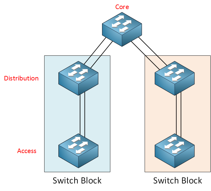 The picture above looks really clean and simple. Each switch picture represents multiple physical switches that have been combined into a single logical switch. The redundant links between each switch pair can be configured as an Etherchannel.
You should now have an idea of the advantages of combining physical switches into logical switches. Cisco offers two technologies that we can use to create logical switches:
I created a Stackwise and VSS lesson so if you are interested, click on the links above to learn more about these two technologies. For now, I hope this has been helpful to understand the advantages of logical switches.
No comments:
Post a Comment