PPP (Point to Point Protocol) was originally used on serial interfaces for point-to-point interfaces. Back in the 90s, PPP was also commonly used for internet dial-up connections. One of the advantages of PPP is that you can use it to assign an IP address to the other end. The most important advantage however, is that you can use CHAP authentication. This allows an ISP to check the username/password of a remote user.
Around the year 2000, we got DSL and cable Internet connections and ISPs wanted to keep using PPP. The issue though is that computers and routers are connected to a DSL/cable modem using Ethernet so it wasn’t possible to use PPP from your computer or router as it had to travel over an Ethernet link. To fix this problem, a new RFC was created for PPPoE (PPP over Ethernet). It allows us to encapsulate PPP into Ethernet frames.
In this lesson, I’ll show you how to configure a PPPoE server and PPPoE client.
Configuration
We will use the following two routers:

We only need two routers…a client and a server, let’s configure the server first.
Server
There are quite some commands required to configure PPPoE. I’ll walk you through the configuration step-by-step.
PPPoE requires a BBA (BroadBand Access) group which is used to establish PPPoE sessions. This is where you can configure session limitations per client and such. You can create multiple BBA groups or use the global BBA group:
Server(config)#bba-group pppoe global
Server(config-bba-group)#virtual-template 1
I’m not going to configure any session limitations but I do have to refer to a virtual-template. The virtual template is where we configure the IP address and some other PPP related settings:
Server(config)#interface virtual-template 1
Server(config-if)#ip address 192.168.12.2 255.255.255.0
Server(config-if)#mtu 1492
Server(config-if)#peer default ip address pool CLIENT
Server(config-if)#ppp authentication chap callin
This is where we configure the IP address for the server and we also have to set the MTU here. Since PPPoE adds another header (8 bytes) we have to reduce the MTU size to 1492. PPP allows us to assign an IP address to a client without using DHCP, which is what we will do here. We refer to a local pool called “CLIENT” that will we configure in a bit. Last but not least, when the client attempts to connect we will authenticate the client.
Let’s configure the local pool:
Server(config)#ip local pool CLIENT 192.168.12.1
Whenever the client connects it will receive IP address 192.168.12.1. You can also use DHCP if you want some more options.
Don’t forget to create a username and password:
Server(config)#username CUSTOMER password CISCO
The last thing we have to do is to enable the BBA group on the interface that connects to the client:
Server(config)#interface GigabitEthernet 0/1
Server(config-if)#pppoe enable group global
That’s all you have to do on the server. Let’s look at the client.
Client
The configuration on the client side is a bit different, it requires a dialer interface. Dialer interfaces were originally used for dial-up connections, nowadays we use them as logical interfaces that can be bound to another interface. In our example, we will use a dialer interface to bind PPP to an Ethernet interface
Here’s what the dialer interface looks like:
Client(config)#interface dialer 1
Client(config-if)#mtu 1492
Client(config-if)#encapsulation ppp
Client(config-if)#ip address negotiated
Client(config-if)#ppp chap hostname CUSTOMER
Client(config-if)#ppp chap password CISCO
Client(config-if)#dialer pool 1
You can pick any number you like for the dialer interface, I chose number 1. The MTU is set to 1492, just like we had to do on the PPPoE server. The IP address is negotiated through PPP. Since the server requires authentication, we configure a CHAP hostname and password here that match the username and password combination that we configured on the server.
The dialer pool command refers to a pool number (one) which is used to link the dialer interface to the physical interface. We will need this number for the physical interface connection:
Client(config)#interface GigabitEthernet 0/1
Client(config-if)#pppoe-client dial-pool-number 1
On the GigabitEthernet interface we use the pppoe-client command to refer to the same pool number as the dialer pool command under the dialer interface. This completes our PPPoE client and server configuration.
Verification
When you complete your configuration, you will see that a new virtual access interface is spawned, which is bound to the dialer interface:
Client#
%DIALER-6-BIND: Interface Vi1 bound to profile Di1
%LINK-3-UPDOWN: Interface Virtual-Access1, changed state to up
%LINEPROTO-5-UPDOWN: Line protocol on Interface Virtual-Access1, changed state to up
I will explain these two interfaces in a bit. First, let’s take a closer look at how the PPPoE session is established. To do this, I will enable debugging on both routers:
Client & Server
#debug ppp negotiation
PPP protocol negotiation debugging is on
Let’s clear the dialer interface so that the session is torn down and reestablished:
Client#clear interface dialer 1
Let’s see what debug information the client produces:
Client#
%DIALER-6-BIND: Interface Vi1 bound to profile Di1
%LINK-3-UPDOWN: Interface Virtual-Access1, changed state to up
Vi1 PPP: Sending cstate UP notification
Vi1 PPP: Processing CstateUp message
PPP: Alloc Context [CEA4634]
ppp5 PPP: Phase is ESTABLISHING
Vi1 PPP: Using dialer call direction
Vi1 PPP: Treating connection as a callout
Vi1 PPP: Session handle[69000005] Session id[5]
Vi1 LCP: Event[OPEN] State[Initial to Starting]
Vi1 PPP: No remote authentication for call-out
Vi1 LCP: O CONFREQ [Starting] id 1 len 14
Vi1 LCP:    MRU 1492 (0x010405D4)
Vi1 LCP:    MagicNumber 0x1671DE19 (0x05061671DE19)
Vi1 LCP: Event[UP] State[Starting to REQsent]
Vi1 LCP: I CONFREQ [REQsent] id 1 len 19
Vi1 LCP:    MRU 1492 (0x010405D4)
Vi1 LCP:    AuthProto CHAP (0x0305C22305)
Vi1 LCP:    MagicNumber 0x16727C43 (0x050616727C43)
Vi1 LCP: O CONFACK [REQsent] id 1 len 19
Vi1 LCP:    MRU 1492 (0x010405D4)
Vi1 LCP:    AuthProto CHAP (0x0305C22305)
Vi1 LCP:    MagicNumber 0x16727C43 (0x050616727C43)
Vi1 LCP: Event[Receive ConfReq+] State[REQsent to ACKsent]
Vi1 LCP: I CONFACK [ACKsent] id 1 len 14
Vi1 LCP:    MRU 1492 (0x010405D4)
Vi1 LCP:    MagicNumber 0x1671DE19 (0x05061671DE19)
Vi1 LCP: Event[Receive ConfAck] State[ACKsent to Open]
Vi1 PPP: Phase is AUTHENTICATING, by the peer
Vi1 LCP: State is Open
Vi1 CHAP: I CHALLENGE id 1 len 27 from "Server"
Vi1 CHAP: Using hostname from interface CHAP
Vi1 CHAP: Using password from interface CHAP
Vi1 CHAP: O RESPONSE id 1 len 29 from "CUSTOMER"
Vi1 CHAP: I SUCCESS id 1 len 4
Vi1 PPP: Phase is FORWARDING, Attempting Forward
Vi1 PPP: Queue IPCP code[1] id[1]
Vi1 PPP: Phase is ESTABLISHING, Finish LCP
%LINEPROTO-5-UPDOWN: Line protocol on Interface Virtual-Access1, changed state to up
Vi1 PPP: Phase is UP
Vi1 IPCP: Protocol configured, start CP. state[Initial]
Vi1 IPCP: Event[OPEN] State[Initial to Starting]
Vi1 IPCP: O CONFREQ [Starting] id 1 len 10
Vi1 IPCP:    Address 0.0.0.0 (0x030600000000)
Vi1 IPCP: Event[UP] State[Starting to REQsent]
Vi1 CDPCP: Protocol configured, start CP. state[Initial]
Vi1 CDPCP: Event[OPEN] State[Initial to Starting]
Vi1 CDPCP: O CONFREQ [Starting] id 1 len 4
Vi1 CDPCP: Event[UP] State[Starting to REQsent]
Vi1 PPP: Process pending ncp packets
Vi1 IPCP: Redirect packet to Vi1
Vi1 IPCP: I CONFREQ [REQsent] id 1 len 10
Vi1 IPCP:    Address 192.168.12.2 (0x0306C0A80C02)
Vi1 IPCP: O CONFACK [REQsent] id 1 len 10
Vi1 IPCP:    Address 192.168.12.2 (0x0306C0A80C02)
Vi1 IPCP: Event[Receive ConfReq+] State[REQsent to ACKsent]
Vi1 IPCP: I CONFNAK [ACKsent] id 1 len 10
Vi1 IPCP:    Address 192.168.12.1 (0x0306C0A80C01)
Vi1 IPCP: O CONFREQ [ACKsent] id 2 len 10
Vi1 IPCP:    Address 192.168.12.1 (0x0306C0A80C01)
Vi1 IPCP: Event[Receive ConfNak/Rej] State[ACKsent to ACKsent]
Vi1 LCP: I PROTREJ [Open] id 2 len 10 protocol CDPCP (0x01010004)
Vi1 CDPCP: Event[Receive CodeRej-] State[REQsent to Stopped]
Vi1 IPCP: I CONFACK [ACKsent] id 2 len 10
Vi1 IPCP:    Address 192.168.12.1 (0x0306C0A80C01)
Vi1 IPCP: Event[Receive ConfAck] State[ACKsent to Open]
Vi1 IPCP: State is Open
Di1 IPCP: Install negotiated IP interface address 192.168.12.1
Di1 Added to neighbor route AVL tree: topoid 0, address 192.168.12.2
Di1 IPCP: Install route to 192.168.12.2
Above we can see that the PPP session is establishing, authentication is done using CHAP and the IP address is negotiated and installed. Here’s the server output:
Server#
PPP: Alloc Context [CEA4634]
ppp5 PPP: Phase is ESTABLISHING
ppp5 PPP: Using vpn set call direction
ppp5 PPP: Treating connection as a callin
ppp5 PPP: Session handle[29000005] Session id[5]
ppp5 LCP: Event[OPEN] State[Initial to Starting]
ppp5 PPP LCP: Enter passive mode, state[Stopped]
ppp5 LCP: I CONFREQ [Stopped] id 1 len 14
ppp5 LCP:    MRU 1492 (0x010405D4)
ppp5 LCP:    MagicNumber 0x1671DE19 (0x05061671DE19)
ppp5 LCP: O CONFREQ [Stopped] id 1 len 19
ppp5 LCP:    MRU 1492 (0x010405D4)
ppp5 LCP:    AuthProto CHAP (0x0305C22305)
ppp5 LCP:    MagicNumber 0x16727C43 (0x050616727C43)
ppp5 LCP: O CONFACK [Stopped] id 1 len 14
ppp5 LCP:    MRU 1492 (0x010405D4)
ppp5 LCP:    MagicNumber 0x1671DE19 (0x05061671DE19)
ppp5 LCP: Event[Receive ConfReq+] State[Stopped to ACKsent]
ppp5 LCP: I CONFACK [ACKsent] id 1 len 19
ppp5 LCP:    MRU 1492 (0x010405D4)
ppp5 LCP:    AuthProto CHAP (0x0305C22305)
ppp5 LCP:    MagicNumber 0x16727C43 (0x050616727C43)
ppp5 LCP: Event[Receive ConfAck] State[ACKsent to Open]
ppp5 PPP: Phase is AUTHENTICATING, by this end
ppp5 CHAP: O CHALLENGE id 1 len 27 from "Server"
ppp5 LCP: State is Open
ppp5 CHAP: I RESPONSE id 1 len 29 from "CUSTOMER"
ppp5 PPP: Phase is FORWARDING, Attempting Forward
ppp5 PPP: Phase is AUTHENTICATING, Unauthenticated User
ppp5 IPCP: Authorizing CP
ppp5 IPCP: CP stalled on event[Authorize CP]
ppp5 IPCP: CP unstall
ppp5 PPP: Phase is FORWARDING, Attempting Forward
Vi1.1 PPP: Phase is AUTHENTICATING, Authenticated User
Vi1.1 CHAP: O SUCCESS id 1 len 4
Vi1.1 PPP: Phase is UP
Vi1.1 IPCP: Protocol configured, start CP. state[Initial]
Vi1.1 IPCP: Event[OPEN] State[Initial to Starting]
Vi1.1 IPCP: O CONFREQ [Starting] id 1 len 10
Vi1.1 IPCP:    Address 192.168.12.2 (0x0306C0A80C02)
Vi1.1 IPCP: Event[UP] State[Starting to REQsent]
Vi1.1 IPCP: I CONFREQ [REQsent] id 1 len 10
Vi1.1 IPCP:    Address 0.0.0.0 (0x030600000000)
Vi1.1 IPCP AUTHOR: Start.  Her address 0.0.0.0, we want 0.0.0.0
Vi1.1 IPCP AUTHOR: Done.  Her address 0.0.0.0, we want 0.0.0.0
Vi1.1 IPCP: Pool returned 192.168.12.1
Vi1.1 IPCP: O CONFNAK [REQsent] id 1 len 10
Vi1.1 IPCP:    Address 192.168.12.1 (0x0306C0A80C01)
Vi1.1 IPCP: Event[Receive ConfReq-] State[REQsent to REQsent]
Vi1.1 CDPCP: I CONFREQ [UNKNOWN] id 1 len 4
Vi1.1 LCP: O PROTREJ [Open] id 2 len 10 protocol CDPCP (0x01010004)
Vi1.1 IPCP: I CONFACK [REQsent] id 1 len 10
Vi1.1 IPCP:    Address 192.168.12.2 (0x0306C0A80C02)
Vi1.1 IPCP: Event[Receive ConfAck] State[REQsent to ACKrcvd]
Vi1.1 IPCP: I CONFREQ [ACKrcvd] id 2 len 10
Vi1.1 IPCP:    Address 192.168.12.1 (0x0306C0A80C01)
Vi1.1 IPCP: O CONFACK [ACKrcvd] id 2 len 10
Vi1.1 IPCP:    Address 192.168.12.1 (0x0306C0A80C01)
Vi1.1 IPCP: Event[Receive ConfReq+] State[ACKrcvd to Open]
Vi1.1 IPCP: State is Open
Vi1.1 Added to neighbor route AVL tree: topoid 0, address 192.168.12.1
Vi1.1 IPCP: Install route to 192.168.12.1
Above we see a similar output. The PPP session is established, the client is authenticated and assigned an IP address. If you want to take a closer look at this PPP session, you can find the wireshark capture of this debug here:
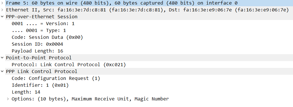
Here’s one packet capture of Wireshark I’d like to show you, it clearly shows how PPP is sitting on top of Ethernet:
Let’s take a look at some show commands on the client. When you work with PPPoE, it will probably be on the client unless you work at an ISP. Let’s take a closer look at the interfaces:
Client#show interfaces dialer 1
Dialer1 is up, line protocol is up (spoofing)
  Hardware is Unknown
  Internet address is 192.168.12.1/32
  MTU 1492 bytes, BW 56 Kbit/sec, DLY 20000 usec,
     reliability 255/255, txload 1/255, rxload 1/255
  Encapsulation PPP, LCP Closed, loopback not set
  Keepalive set (10 sec)
  DTR is pulsed for 1 seconds on reset
  Interface is bound to Vi1
  Last input never, output never, output hang never
  Last clearing of "show interface" counters 00:41:30
  Input queue: 0/75/0/0 (size/max/drops/flushes); Total output drops: 0
  Queueing strategy: fifo
  Output queue: 0/40 (size/max)
  5 minute input rate 0 bits/sec, 0 packets/sec
  5 minute output rate 0 bits/sec, 0 packets/sec
     8 packets input, 552 bytes
     456 packets output, 6924 bytes
Bound to:
Virtual-Access1 is up, line protocol is up
  Hardware is Virtual Access interface
  MTU 1492 bytes, BW 56 Kbit/sec, DLY 20000 usec,
     reliability 255/255, txload 1/255, rxload 1/255
  Encapsulation PPP, LCP Open
  Stopped: CDPCP
  Open: IPCP
  PPPoE vaccess, cloned from Dialer1
  Vaccess status 0x44, loopback not set
  Keepalive set (10 sec)
  Interface is bound to Di1 (Encapsulation PPP)
  Last input 00:00:04, output never, output hang never
  Last clearing of "show interface" counters 00:01:37
  Input queue: 0/75/0/0 (size/max/drops/flushes); Total output drops: 0
  Queueing strategy: fifo
  Output queue: 0/40 (size/max)
  5 minute input rate 0 bits/sec, 0 packets/sec
  5 minute output rate 0 bits/sec, 0 packets/sec
     22 packets input, 316 bytes, 0 no buffer
     Received 0 broadcasts (0 IP multicasts)
     0 runts, 0 giants, 0 throttles
     0 input errors, 0 CRC, 0 frame, 0 overrun, 0 ignored, 0 abort
     21 packets output, 306 bytes, 0 underruns
     0 output errors, 0 collisions, 0 interface resets
     0 unknown protocol drops
     0 output buffer failures, 0 output buffers swapped out
     0 carrier transitions
Above we see the output of the show interface dialer command. It shows us information about the dialer and virtual-access interfaces. The dialer interface gives us all layer 3 information, the virtual-access interface gives us layer 2 information.
The first part about the dialer interface tells us that the interface is up and that the line protocol is also up, which means that PPPoE is working. We can see the MTU of 1492 that we configured and the IP address that the client received (192.168.12.1). It uses PPP encapsulation and LCP shows up as closed. This is because the dialer interface doesn’t do any of the PPP-related tasks, that’s something the virtual-access interface does.
The output also tells us that the dialer interface is bound to the virtual access 1 interface. The second part of the output shows information about the virtual-access interface. This is the layer 2 interface and it takes care of all PPP-related tasks, which is why LCP shows up as open here.
The show interfaces dialer command gives us information about both interfaces, there is also a command that only shows information about the virtual-access interface:
Client#show interfaces virtual-access 1
Virtual-Access1 is up, line protocol is up
  Hardware is Virtual Access interface
  MTU 1492 bytes, BW 56 Kbit/sec, DLY 20000 usec,
     reliability 255/255, txload 1/255, rxload 1/255
  Encapsulation PPP, LCP Open
  Stopped: CDPCP
  Open: IPCP
  PPPoE vaccess, cloned from Dialer1
  Vaccess status 0x44, loopback not set
  Keepalive set (10 sec)
  Interface is bound to Di1 (Encapsulation PPP)
  Last input 00:00:01, output never, output hang never
  Last clearing of "show interface" counters 00:03:13
  Input queue: 0/75/0/0 (size/max/drops/flushes); Total output drops: 0
  Queueing strategy: fifo
  Output queue: 0/40 (size/max)
  5 minute input rate 0 bits/sec, 0 packets/sec
  5 minute output rate 0 bits/sec, 0 packets/sec
     42 packets input, 596 bytes, 0 no buffer
     Received 0 broadcasts (0 IP multicasts)
     0 runts, 0 giants, 0 throttles
     0 input errors, 0 CRC, 0 frame, 0 overrun, 0 ignored, 0 abort
     41 packets output, 586 bytes, 0 underruns
     0 output errors, 0 collisions, 0 interface resets
     0 unknown protocol drops
     0 output buffer failures, 0 output buffers swapped out
     0 carrier transitions
Both interfaces show up if you look at the available interfaces on your router:
Client#show ip interface brief
Interface                  IP-Address      OK? Method Status                Protocol
GigabitEthernet0/0         unassigned      YES unset  administratively down down
GigabitEthernet0/1         unassigned      YES unset  up                    up
Dialer1                    192.168.12.1    YES IPCP   up                    up
Virtual-Access1            unassigned      YES unset  up                    up
The virtual-access interface is created dynamically by the router based on the information in the dialer interface. There is a show command you can use to see the actual commands that are used:
Client#show interfaces virtual-access 1 configuration
Virtual-Access1 is a PPP over Ethernet link (sub)interface

Derived configuration : 112 bytes
!
interface Virtual-Access1
 mtu 1492
 ppp chap hostname CUSTOMER
 ppp chap password 0 CISCO
 pulse-time 0
end
There is one show command that gives us a nice overview of all interfaces that are used in a single PPPoE session:
Client#show pppoe session
     1 client session

Uniq ID  PPPoE  RemMAC          Port                    VT  VA         State
           SID  LocMAC                                      VA-st      Type
    N/A      4  fa16.3ee9.067e  Gi0/1                   Di1 Vi1        UP
                fa16.3e7d.c881                              UP
Above you can see the Gigabit Ethernet interface, the MAC addresses of the Gigabit interfaces, the dialer 1 interface and the virtual-access 1 interface.
The dialer interface is our layer 3 interface which has the IP address. It’s the interface you will find in the routing table:
Client#show ip route connected

      192.168.12.0/32 is subnetted, 2 subnets
C        192.168.12.1 is directly connected, Dialer1
That’s all we have on PPPoE for now.
hostname Client
!
ip cef
!
interface GigabitEthernet0/1
 no ip address
 pppoe enable group global
 pppoe-client dial-pool-number 1
!
interface Dialer1
 mtu 1492
 ip address negotiated
 encapsulation ppp
 dialer pool 1
 ppp chap hostname CUSTOMER
 ppp chap password 0 CISCO
!
end
hostname Server
!
ip cef
username CUSTOMER password 0 CISCO
!
bba-group pppoe global
virtual-template 1
!
interface GigabitEthernet0/1
no ip address
pppoe enable group global
!
interface Virtual-Template1
mtu 1492
ip address 192.168.12.2 255.255.255.0
peer default ip address pool CLIENT
ppp authentication chap callin
!
ip local pool CLIENT 192.168.12.1
!
endConclusion
PPPoE allows us to run PPP over Ethernet interfaces. It is used often for DSL / Cable Internet but we can also configure it on regular Ethernet interfaces.
On the server side, we have to configure a virtual-template that is attached to a BBA group. The virtual template has all IP and PPP settings. The virtual-template is attached to an Ethernet interface by using the pppoe enable command and refering to the BBA group.
The client is configured with a dialer interface that has all IP and PPP settings. The dialer interface is attached to the Ethernet interface with the pppoe-client command.
Once the PPPoE session is established, the client creates a virtual-access interface. The dialer interface will have all layer 3 information, the virtual-access interface has all layer two information.
No comments:
Post a Comment