router isis 1234
advertise passive-only
passive-interface Loopback0
advertise passive-only:即只通告设置为被动口的路由(如果你把loopback口设置为被动口,那么只通告loopback口的路由出去)
Wednesday, December 4, 2019
Tuesday, December 3, 2019
CCIE LAB
考试内容:
1、TS(Troubleshooting)故障排错
考察排除网络故障的能力。考试模拟网络环境,比如某台服务器不能访问,让你找出问题并解决。改模块需要在设备上配置。
2、DIAG(Diagnose)故障诊断
考察网络故障分析能力。这个模块是没有设备操作,考场会给你网络需求、问题,给出设备的配置,日志信息,让你分析网络故障发生的原因。该模块没有设备可以配置。
3、CFG(Configuration)配置:
考察构建网络的能力,考场给出需求,拓扑,按照要求完成网络搭建。该模块需要在设备上配置。
分数分布和通过分数:
CCIE LAB 考试分数总分100分,每个模块需>=80%才能拿到CCIE证书。
TS(Troubleshooting)故障排错的的总分是24分,要求该模块>=20分,才能通过CCIE考试。
DIAG(Diagnose)故障诊断的总分是6分,要求该模块>=4分,才能通过CCIE考试。
CFG(Configuration)配置的总分是70分,要求该模块>=56分,才能通过CCIE考试。
考试时间:
CCIE LAB考试时间为8小时。
TS(Troubleshooting)故障排错的考试时间最多可以用到2.5小时,也可以提早结束该模块考试,如1.5H做好,可以直接选择结束该模块考试进入到下个模块。
DIAG(Diagnose)故障诊断考试时间固定0.5小时,不能提早结束。
CFG(Configuration)配置的考试时间是总时长8小时扣掉TS和DIAG的时长。
PS:TS最多可以用到2.5小时。
双出口NAT
+------+     +------+
| ISPA |     | ISPB |
+-----++     +-+----+
      |        |
     ++--------++
     |  2960    |
     +----+-----+
          |
      +---+---+
      | 4451  |
      +---+---+
          |
          |
       +--+---+
       | 3925 |
       +------+


track 1 ip sla 1 reachability
track 2 ip sla 2 reachability
interface GigabitEthernet0/0/0
interface GigabitEthernet0/0/0.10
encapsulation dot1Q 10
ip address dhcp
ip nat outside
!
interface GigabitEthernet0/0/0.20
encapsulation dot1Q 20
ip address dhcp
ip nat outside
!
interface GigabitEthernet0/0/1
ip address 192.168.1.1 255.255.255.0
ip nat inside
ip policy route-map Lan
load-interval 30
negotiation auto
!
ip nat inside source route-map nat interface GigabitEthernet0/0/0.10 overload
ip nat inside source route-map nat2 interface GigabitEthernet0/0/0.20 overload
ip route 0.0.0.0 0.0.0.0 10.1.1.1 10 track 1
ip route 0.0.0.0 0.0.0.0 10.1.2.1 20 track 2
!
ip access-list extended nat           //please use acl like this, permit icmp XXX, permit TCP XXX, permit udp XXXX
permit icmp 192.168.1.0 0.0.0.255 any
permit tcp 192.168.1.0 0.0.0.255 any
permit udp 192.168.1.0 0.0.0.255 any
ip access-list extended test
permit icmp 192.168.1.0 0.0.0.255 any
permit tcp 192.168.1.0 0.0.0.255 any
permit udp 192.168.1.0 0.0.0.255 any
ip sla 1
icmp-echo 10.1.1.1 source-interface GigabitEthernet0/0/0.10
frequency 5
ip sla schedule 1 life forever start-time now
ip sla 2
icmp-echo 10.1.2.1 source-interface GigabitEthernet0/0/0.20
frequency 5
ip sla schedule 2 life forever start-time now
!
route-map Lan permit 10
match ip address test
set ip next-hop verify-availability 10.1.1.1 10 track 1
set ip next-hop verify-availability 10.1.2.1 20 track 2
!
route-map nat2 permit 10
match ip address nat
match interface GigabitEthernet0/0/0.20
!
route-map nat permit 10
match ip address nat
match interface GigabitEthernet0/0/0.10
!

--------------------------------------------
Test:
1. Test the ISP A failed:
1.  Check router interface:
Router#show ip int b
Interface              IP-Address      OK? Method Status                Protocol
GigabitEthernet0/0/0   unassigned      YES NVRAM  up                    up
Gi0/0/0.10             unassigned      YES DHCP   up                    up      <<<<<<<<<<<<< ISP A, due to ISP issue, not receive the dhcp address.
Gi0/0/0.20             10.1.2.4        YES DHCP   up                    up      <<<<<<<<<<<<< ISP B
GigabitEthernet0/0/1   192.168.1.1     YES NVRAM  up                    up
  1.  Simulator the PC access network
C10-RU09-3925#ping 8.8.8.8
Type escape sequence to abort.
Sending 5, 100-byte ICMP Echos to 8.8.8.8, timeout is 2 seconds:
!!!!!
Success rate is 100 percent (5/5), round-trip min/avg/max = 1/1/1 ms
  1.  Check nat translation:
Router#show ip nat translations
Pro  Inside global         Inside local          Outside local         Outside global
icmp 10.1.2.4:55           192.168.1.10:55       8.8.8.8:55            8.8.8.8:55
tcp  10.1.2.4:5064         192.168.1.10:33231    10.124.41.40:49       10.124.41.40:49
udp  10.1.2.4:512          192.168.1.10:123      10.64.58.51:123       10.64.58.51:123
icmp 10.1.2.4:53           192.168.1.10:53       192.168.1.1:53        192.168.1.1:53
tcp  10.1.2.4:5063         192.168.1.10:26148    10.124.41.40:49       10.124.41.40:49
  1.  Check route-map :
route-map Lan, permit, sequence 10
  Match clauses:
    ip address (access-lists): test
  Set clauses:
    ip next-hop verify-availability 10.1.1.1 10 track 1  [down] <<<<<<<<<<<<<ISPA track down, the isp failed.
    ip next-hop verify-availability 10.1.2.1 20 track 2  [up]
  Policy routing matches: 29 packets, 2698 bytes           <<<<<<<<<<<<<this counter will increase
route-map nat2, permit, sequence 10
  Match clauses:
    ip address (access-lists): nat
    interface GigabitEthernet0/0/0.20
  Set clauses:
  Policy routing matches: 0 packets, 0 bytes
route-map nat, permit, sequence 10
  Match clauses:
    ip address (access-lists): nat
    interface GigabitEthernet0/0/0.10
  Set clauses:
  Policy routing matches: 0 packets, 0 bytes
Resume the ISP A:
  1.  Found the interface connected to ISP A interface received an ip address log:
*Sep 23 12:33:33.727: %DHCP-6-ADDRESS_ASSIGN: Interface GigabitEthernet0/0/0.10 assigned DHCP address 10.1.1.4, mask 255.255.255.0, hostname Router
2. DHCP status:
Router# show dhcp lease
Temp IP addr: 10.1.2.4  for peer on Interface: GigabitEthernet0/0/0.20
Temp  sub net mask: 255.255.255.0
   DHCP Lease server: 10.1.2.1, state: 5 Bound
   DHCP transaction id: 1BDC
   Lease: 86400 secs,  Renewal: 43200 secs,  Rebind: 75600 secs
   Next timer fires after: 11:57:32
   Retry count: 0   Client-ID: cisco-00fe.c8cd.9ef0-Gi0/0/0.20
   Client-ID hex dump: 636973636F2D303066652E633863642E
                       396566302D4769302F302F302E3230
   Hostname: Router
Temp IP addr: 10.1.1.4  for peer on Interface: GigabitEthernet0/0/0.10
Temp  sub net mask: 255.255.255.0
   DHCP Lease server: 10.1.1.1, state: 5 Bound
   DHCP transaction id: 1BE0
   Lease: 86400 secs,  Renewal: 43200 secs,  Rebind: 75600 secs
Temp default-gateway addr: 10.3.3.1
   Next timer fires after: 11:59:56
   Retry count: 0   Client-ID: cisco-00fe.c8cd.9ef0-Gi0/0/0.10
   Client-ID hex dump: 636973636F2D303066652E633863642E
                       396566302D4769302F302F302E3130
   Hostname: Router
  1.  Default route changed from 10.1.2.1 to 10.1.1.1            //the default router change need the sla status and track status changed, the track status need up.
Router#show ip route
<snip>
Gateway of last resort is 10.1.2.1 to network 0.0.0.0
S*    0.0.0.0/0 [20/0] via 10.1.2.1
      10.0.0.0/8 is variably subnetted, 4 subnets, 2 masks
Router#show ip route
<snip>
Gateway of last resort is 10.1.1.1 to network 0.0.0.0
S*    0.0.0.0/0 [10/0] via 10.1.1.1
Log: *Sep 23 12:33:46.780: %TRACK-6-STATE: 1 ip sla 1 reachability Down -> Up
  1.  Check NAT translation:
a)   Router#clear ip nat translation * // clear ip nat record
b)   Use client access the network:
C10-RU09-3925#ping 8.8.8.8
Type escape sequence to abort.
Sending 5, 100-byte ICMP Echos to 8.8.8.8, timeout is 2 seconds:
!!!!!
c)   Check nat record on router:
Router#show ip nat translations
Pro  Inside global         Inside local          Outside local         Outside global
tcp  10.1.1.4:5062         192.168.1.10:42040    10.124.41.40:49       10.124.41.40:49
icmp 10.1.1.4:58           192.168.1.10:58       8.8.8.8:58            8.8.8.8:58
Total number of translations: 2
d)   Route-map counter:
Router#show route-map
route-map Lan, permit, sequence 10
  Match clauses:
    ip address (access-lists): test
  Set clauses:
    ip next-hop verify-availability 10.1.1.1 10 track 1  [up]          //the track 1 & track 2 is up, but the ISP A is high priority internet output
   ip next-hop verify-availability 10.1.2.1 20 track 2  [up]
  Policy routing matches: 44 packets, 4160 bytes           //counter increase
route-map nat2, permit, sequence 10
  Match clauses:
    ip address (access-lists): nat
    interface GigabitEthernet0/0/0.20
  Set clauses:
  Policy routing matches: 0 packets, 0 bytes
route-map nat, permit, sequence 10
  Match clauses:
    ip address (access-lists): nat
    interface GigabitEthernet0/0/0.10
  Set clauses:
  Policy routing matches: 0 packets, 0 bytes
Update: please use like this access:
ip access-list extended test
deny   icmp 192.168.1.0 0.0.0.255 host 192.168.1.1        //deny the source access to the router connection address , if not, you cannot ping the router connection address, like ping 192.168.1.1 so 192.168.1.10, If not deny, the source will math the below list and it will send to nat process, but this is access to the router link address, it will be drop.
permit icmp 192.168.1.0 0.0.0.255 any
permit tcp 192.168.1.0 0.0.0.255 any
permit udp 192.168.1.0 0.0.0.255 any
Thursday, October 31, 2019
94230-00000-d41d8
D4679267A355B275893A9031A306E02181629164A55AAF70832F9065F453B4258266C3947ADA619173
80619A6DA453B077823A976DA601E12181629164A55AAF70832F9164F453E1798035C3947ADA619173
80619A6DA453B077823A976DA601E12181629164A55AAF70832F9164F453E1798035C3947ADA619173
IS-IS IPv6 Support - Single Topology vs Multi-Topology
本文档的目的是说明单拓扑和多拓扑路由的SPF差异,以及在为IS-IS(中间系统到中间系统)添加IPv6支持时如何同时使用这两种方法。本文档还将涵盖在IOS,IOS XE和IOS XR中发现的用于实现此技术的语法差异,因为默认情况下,除非已设置正确的路由模式,否则IS-IS中与IPv6的互操作将在这些平台上不起作用。
先决条件
对IS-IS操作的基本了解
了解SPF图论及其与IS-IS和OSPF的相互作用
基本了解路由原理
尽管不是强制性的,但了解IOS XR语法是建议性的
单拓扑路由
单个拓扑路由是在其中构建单个图/拓扑的情况,通过该图/拓扑将不同的地址族(IPv4 / IPv6)作为树的“叶子”施加在顶部。如果单个节点或链路发生故障,则IPv4和IPv6路由都可能受到影响,它们的收敛方式相同。这是因为在通过SPF状态机计算LSDB(链接状态数据库)时,会为IPv4和IPv6生成单个拓扑。关于OSPF和IS-IS,这意味着在链路状态刷新或任何引起SPF计算的事件中,两个地址族都必须进行一次运行,因此使协议可以更有效地从CPU运行透视。此实现的主要缺点是IPv4和IPv6需要以1:1的方式运行,并且每个IPv4链接都需要一个IPv6副本。否则,可能会导致特定地址族的流量出现黑洞。例如,如果同时运行IPv4和IPv6的链接失败,则SPF可能会故障转移到仅运行IPv4的备份链接。由于仅使用单个拓扑,因此IPv6将无法收敛,因为最短路径计算会影响两个地址族。除此之外,如果管理员希望IPv4和IPv6采取通往特定节点的单独路由,则更难以实现流量工程要求。
多拓扑路由
多拓扑路由是将地址族与单个SPF图解耦的过程,而是为每个地址族生成多个SPF图。此方法减轻了与流量工程和流量下降有关的所有问题,因为IPv4和IPv6不需要以1:1的方式处理。对于许多仍在推出IPv6或尚未推出IPv6的组织而言,这种方法使MTR成为更合适的部署。这样做的唯一缺点是,需要使用更多的CPU周期来管理现在制作的各种SPF图形。同样,状态更改将调用两倍于需要用该更改更新的图形的CPU能力。
一个有趣的注释是,如果您正在运行OSPF,则您已经在作为独立的控制平面协议运行多拓扑路由,因此,OSPF使用了独立的图形(OSPFv2和OPSFv3)。如果两个地址族都使用OSPFv3,那么您仍将使用多个拓扑。此决定严格限于IS-IS(基于QoS的MTR除外)。由于IS-IS是具有新TLV(类型,长度值)选项的可扩展协议,因此决定运行单拓扑还是多拓扑成为管理员的选择。


总结一下,请参见下图,以了解差异的概念。

IOS,IOS XE和IOS XR互操作
为了帮助我演示IS-IS for IPv6在各种IOS平台上的互操作性,我将使用以下所示的拓扑:

为了帮助概述此部署中IS-IS的基本配置,我将展示IOS / IOS-XE和IOS-XR的基本配置。
以下配置已通过接口值和NET(网络实体标题)进行相应调整而应用于R1和R2。
R1和R2
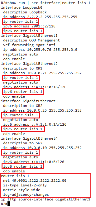
路由过程从基本NET开始,并且像往常一样定义为type。 需要注意的一件事是,必须将度量标准样式设置为宽以支持多拓扑路由。 然后针对每个接口分别针对IPv4和IPv6激活该过程。
对于XR1和XR2

OS-XR语法是分层的,因此将整个过程保持在一个部分之下。 但是,目标是相同的,即为IPv4和IPv6启用IS-IS。
作为配置的结果,可能指示拓扑选择不匹配的第一个符号是在R1和R2上生成的日志消息。

注意:默认情况下,IOS和IOS XR不执行IS-IS进程的日志记录,将分别需要路由器配置命令log-adjacency-changes和log邻接更改。
拓扑类型不匹配的另一个迹象是,没有在IPv6的RIB(路由信息库)中安装路由。

与R1相比,进一步检查XR1的LSP(链路状态数据包)将提供有关此问题的更多详细信息。

可以看出,XR1尝试运行MTR,而R1使用单拓扑。 这显示了默认配置如何破坏IS-IS中的IPv6可达性。 IOS-XR默认为MTR,而IOS和IOS XE默认为单拓扑。
配置单一拓扑
由于IOS默认为单一拓扑,因此在IOS-XR上只需要更改一个配置即可支持它。 然后,这将允许处理IPv6路由。

现在,IPv4和IPv6都在一个SPF图下运行,并获得了可达性。


配置多拓扑
对于此配置,我已还原XR1和XR2上的配置更改。 除此之外,我还对拓扑进行了调整,以允许我们配置用于IPv4和IPv6的单独路径。 反过来,允许我们在单个路由过程中使用多个拓扑来执行流量工程。

和以前一样,由于IOS-XR默认为多拓扑路由。在IOS上启用它所需的唯一配置更改是地址系列下的单个命令。以下配置同时应用于R1和R2。

应用此功能后,我们现在可以看到R1和R2的LSP已更新为包含MTR TLV。

现在,为每个地址族构建了多个SPF图,这意味着我们现在可以彼此独立地影响每个地址族路由决策。 例如,以下配置应用于R1。 每个链路度量均根据该图进行了调整,因此,IPv4的路由选择的是顶部路由,而IPv6的路由选择了第二条路由。

添加此更改后,我们可以立即看到从R1到Client-2的路由分别针对IPv4和IPv6进行了更改

最后的验证是执行从客户端1到客户端2的跟踪路由。

摘要
在本文档中,我们看到了将IPv6引入IS-IS时如何选择配置拓扑类型的方法。 我们还从概念角度研究了这些差异以及在操作模式之间切换所需的相关配置。 否则,可能会导致流量工程复杂化或使用多个平台的情况; 一个交通黑洞。
https://learningnetwork.cisco.com/docs/DOC-28354
先决条件
对IS-IS操作的基本了解
了解SPF图论及其与IS-IS和OSPF的相互作用
基本了解路由原理
尽管不是强制性的,但了解IOS XR语法是建议性的
单拓扑路由
单个拓扑路由是在其中构建单个图/拓扑的情况,通过该图/拓扑将不同的地址族(IPv4 / IPv6)作为树的“叶子”施加在顶部。如果单个节点或链路发生故障,则IPv4和IPv6路由都可能受到影响,它们的收敛方式相同。这是因为在通过SPF状态机计算LSDB(链接状态数据库)时,会为IPv4和IPv6生成单个拓扑。关于OSPF和IS-IS,这意味着在链路状态刷新或任何引起SPF计算的事件中,两个地址族都必须进行一次运行,因此使协议可以更有效地从CPU运行透视。此实现的主要缺点是IPv4和IPv6需要以1:1的方式运行,并且每个IPv4链接都需要一个IPv6副本。否则,可能会导致特定地址族的流量出现黑洞。例如,如果同时运行IPv4和IPv6的链接失败,则SPF可能会故障转移到仅运行IPv4的备份链接。由于仅使用单个拓扑,因此IPv6将无法收敛,因为最短路径计算会影响两个地址族。除此之外,如果管理员希望IPv4和IPv6采取通往特定节点的单独路由,则更难以实现流量工程要求。
多拓扑路由
多拓扑路由是将地址族与单个SPF图解耦的过程,而是为每个地址族生成多个SPF图。此方法减轻了与流量工程和流量下降有关的所有问题,因为IPv4和IPv6不需要以1:1的方式处理。对于许多仍在推出IPv6或尚未推出IPv6的组织而言,这种方法使MTR成为更合适的部署。这样做的唯一缺点是,需要使用更多的CPU周期来管理现在制作的各种SPF图形。同样,状态更改将调用两倍于需要用该更改更新的图形的CPU能力。
一个有趣的注释是,如果您正在运行OSPF,则您已经在作为独立的控制平面协议运行多拓扑路由,因此,OSPF使用了独立的图形(OSPFv2和OPSFv3)。如果两个地址族都使用OSPFv3,那么您仍将使用多个拓扑。此决定严格限于IS-IS(基于QoS的MTR除外)。由于IS-IS是具有新TLV(类型,长度值)选项的可扩展协议,因此决定运行单拓扑还是多拓扑成为管理员的选择。
总结一下,请参见下图,以了解差异的概念。
IOS,IOS XE和IOS XR互操作
为了帮助我演示IS-IS for IPv6在各种IOS平台上的互操作性,我将使用以下所示的拓扑:
为了帮助概述此部署中IS-IS的基本配置,我将展示IOS / IOS-XE和IOS-XR的基本配置。
以下配置已通过接口值和NET(网络实体标题)进行相应调整而应用于R1和R2。
R1和R2
路由过程从基本NET开始,并且像往常一样定义为type。 需要注意的一件事是,必须将度量标准样式设置为宽以支持多拓扑路由。 然后针对每个接口分别针对IPv4和IPv6激活该过程。
对于XR1和XR2
OS-XR语法是分层的,因此将整个过程保持在一个部分之下。 但是,目标是相同的,即为IPv4和IPv6启用IS-IS。
作为配置的结果,可能指示拓扑选择不匹配的第一个符号是在R1和R2上生成的日志消息。
注意:默认情况下,IOS和IOS XR不执行IS-IS进程的日志记录,将分别需要路由器配置命令log-adjacency-changes和log邻接更改。
拓扑类型不匹配的另一个迹象是,没有在IPv6的RIB(路由信息库)中安装路由。
与R1相比,进一步检查XR1的LSP(链路状态数据包)将提供有关此问题的更多详细信息。
可以看出,XR1尝试运行MTR,而R1使用单拓扑。 这显示了默认配置如何破坏IS-IS中的IPv6可达性。 IOS-XR默认为MTR,而IOS和IOS XE默认为单拓扑。
配置单一拓扑
由于IOS默认为单一拓扑,因此在IOS-XR上只需要更改一个配置即可支持它。 然后,这将允许处理IPv6路由。
现在,IPv4和IPv6都在一个SPF图下运行,并获得了可达性。
配置多拓扑
对于此配置,我已还原XR1和XR2上的配置更改。 除此之外,我还对拓扑进行了调整,以允许我们配置用于IPv4和IPv6的单独路径。 反过来,允许我们在单个路由过程中使用多个拓扑来执行流量工程。
和以前一样,由于IOS-XR默认为多拓扑路由。在IOS上启用它所需的唯一配置更改是地址系列下的单个命令。以下配置同时应用于R1和R2。
应用此功能后,我们现在可以看到R1和R2的LSP已更新为包含MTR TLV。
现在,为每个地址族构建了多个SPF图,这意味着我们现在可以彼此独立地影响每个地址族路由决策。 例如,以下配置应用于R1。 每个链路度量均根据该图进行了调整,因此,IPv4的路由选择的是顶部路由,而IPv6的路由选择了第二条路由。
添加此更改后,我们可以立即看到从R1到Client-2的路由分别针对IPv4和IPv6进行了更改
最后的验证是执行从客户端1到客户端2的跟踪路由。
摘要
在本文档中,我们看到了将IPv6引入IS-IS时如何选择配置拓扑类型的方法。 我们还从概念角度研究了这些差异以及在操作模式之间切换所需的相关配置。 否则,可能会导致流量工程复杂化或使用多个平台的情况; 一个交通黑洞。
https://learningnetwork.cisco.com/docs/DOC-28354
Friday, October 18, 2019
WCCP auto tunnel
The tunnel interfaces are automatically created in order to process outgoing GRE-encapsulated traffic for WCCP. The tunnel interfaces appear when a content engine connects and requests GRE redirection. The tunnel interfaces are not created directly by WCCP, but are created indirectly via a tunnel application programming interface (API). WCCP does not have direct knowledge of the tunnel interfaces, but can redirect packets to them, resulting in the appropriate encapsulation being applied to the packets. After the appropriate encapsulation is applied, the packet is then sent to the content engine.

One tunnel is created for each service group that is using GRE redirection. One additional tunnel is created to provide an IP address that allows the other tunnel group interfaces to be unnumbered but still enabled for IPv4.

You can confirm the connection between the tunnels and WCCP by entering the 'show tunnel groups wccp' command
Tuesday, August 20, 2019
Router# disconnect 1
Command or Action
Ensures that the switch stays at the boot loader prompt, so that you can copy a new image through the Xmodem Protocol.
Starts the file transfer from the router flash memory by using the Xmodem Protocol from the router prompt.
Note Use this command to download the software image from the router flash memory. Use this command from the router prompt.
Note Use this command to download the software image from a TFTP server. Use this command only if the image is not on the router flash memory.
Monday, August 19, 2019
思科NAT默认时间
思科默认NAT timeout
Defaults
timeout: 86,400 seconds (24 hours)
udp-timeout: 300 seconds (5 minutes)
dns-timeout: 60 seconds (1 minute)
tcp-timeout: 86,400 seconds (24 hours)
finrst-timeout: 60 seconds (1 minute)
icmp-timeout: 60 seconds (1 minute)
pptp-timeout: 86,400 seconds (24 hours)
syn-timeout: 60 seconds (1 minute)
seconds: 0 (never)
具体优化需要根据实际业务应用而定!如果没有特别需求,可以将其修改为:
TCP会话老化时间为300秒
UDP会话老化时间为180秒
PPTP会话老化时间为300秒
修改ICMP会话老化时间为10秒
修改DNS会话老化时间为10秒
修改tcp-syn报文老化时间为10秒
TCP会话老化时间为300秒
UDP会话老化时间为180秒
PPTP会话老化时间为300秒
修改ICMP会话老化时间为10秒
修改DNS会话老化时间为10秒
修改tcp-syn报文老化时间为10秒
经验是nat的问题,可以限制并发nat数和nat的有效时间,例如
ip nat translation timeout 180
ip nat translation tcp-timeout 180
ip nat translation udp-timeout 180
ip nat translation syn-timeout 20
ip nat translation icmp-timeout 10
ip nat translation max-entries 10000
ip nat translation timeout 180
ip nat translation tcp-timeout 180
ip nat translation udp-timeout 180
ip nat translation syn-timeout 20
ip nat translation icmp-timeout 10
ip nat translation max-entries 10000
Sunday, August 11, 2019
DNS
chown root:named test.com.zone
2.7 重启
systemctl restart named
2.8 设置开机启动
systemctl enable named
2.9 防火墙开放53、953端口
firewall-cmd --add-port=53/tcp --permanent
firewall-cmd --add-port=53/udp --permanent
firewall-cmd --add-port=953/tcp --permanent
firewall-cmd --reload
2.10 关闭selinux
修改SELNUX的值,wq保存。
SELINUX=disabled
重启OS
shutdown -r now
五、错误排查因为BIND服务的主配置文件 named.conf 以及我们的 zone 配置文件其内容非常复杂,晦涩难懂,所以难免会出现配置出错的情况,因此为了方便我们进行错误排查,BIND还提供了两个非常的命令来对我们的 named.conf 和 zone 文件进行排错检查①命令 named-checkconf 可以查看BIND的主配置文件的错误:[root@xiaoluo named]# named-checkconf /var/named/chroot/etc/named.conf②命令 named-checkzone 可以查看zone配置文件的错误:[root@xiaoluo named]# named-checkzone cnblogs.com.zone /var/named/chroot/var/named/cnblogs.com.zone zone cnblogs.com.zone/IN: loaded serial 0 OK通过这两个命令我们就可以在配置完BIND主配置文件以及zone文件以后对其进行文件排查了,如果没有返回信息,则表示配置没有问题
dns /var/named/rp.zone
[root@localhost ~]# cat /var/named/rp.zone
$TTL 1D
@ IN SOA rp. root (
1 ; serial
1D ; refresh
1H ; retry
1W ; expire
0 ) ; minimum
IN NS rp.
IN A 10.75.49.248
vcsa IN A 10.75.49.246
esx1 IN A 10.75.49.253
esx2 IN A 10.75.49.252
dns IN A 10.75.49.248
$TTL 1D
@ IN SOA rp. root (
1 ; serial
1D ; refresh
1H ; retry
1W ; expire
0 ) ; minimum
IN NS rp.
IN A 10.75.49.248
vcsa IN A 10.75.49.246
esx1 IN A 10.75.49.253
esx2 IN A 10.75.49.252
dns IN A 10.75.49.248
DNS /var/named/10.75.49.zone
[root@localhost ~]# cat /var/named/10.75.49.zone
$TTL 1D
@ IN SOA dns.rp. dns.rp. (
20171224 ; serial
1D ; refresh
1H ; retry
1W ; expire
3H ) ; minimum
@ NS rp.
248 IN PTR dns.rp.
246 IN PTR vcsa.rp.
253 IN PTR esx1.rp.
252 IN PTR esx2.rp.
$TTL 1D
@ IN SOA dns.rp. dns.rp. (
20171224 ; serial
1D ; refresh
1H ; retry
1W ; expire
3H ) ; minimum
@ NS rp.
248 IN PTR dns.rp.
246 IN PTR vcsa.rp.
253 IN PTR esx1.rp.
252 IN PTR esx2.rp.
DNS /etc/named.rfc1912.zones
zone "rp" IN {
type master;
file "rp.zone";
allow-update { none; };
};
zone "49.75.10.in-addr.arpa" IN {
type master;
file "10.75.49.zone";
allow-update { none; };
};
DNS named.conf
[root@localhost ~]# cat /etc/named.conf
//
// named.conf
//
// Provided by Red Hat bind package to configure the ISC BIND named(8) DNS
// server as a caching only nameserver (as a localhost DNS resolver only).
//
// See /usr/share/doc/bind*/sample/ for example named configuration files.
//
// See the BIND Administrator's Reference Manual (ARM) for details about the
// configuration located in /usr/share/doc/bind-{version}/Bv9ARM.html
options {
listen-on port 53 { any; };
listen-on-v6 port 53 { ::1; };
directory "/var/named";
dump-file "/var/named/data/cache_dump.db";
statistics-file "/var/named/data/named_stats.txt";
memstatistics-file "/var/named/data/named_mem_stats.txt";
recursing-file "/var/named/data/named.recursing";
secroots-file "/var/named/data/named.secroots";
allow-query { any; };
forwarders { 64.104.123.245; };
/*
- If you are building an AUTHORITATIVE DNS server, do NOT enable recursion.
- If you are building a RECURSIVE (caching) DNS server, you need to enable
recursion.
- If your recursive DNS server has a public IP address, you MUST enable access
control to limit queries to your legitimate users. Failing to do so will
cause your server to become part of large scale DNS amplification
attacks. Implementing BCP38 within your network would greatly
reduce such attack surface
*/
recursion yes;
dnssec-enable no;
dnssec-validation no;
/* Path to ISC DLV key */
bindkeys-file "/etc/named.iscdlv.key";
managed-keys-directory "/var/named/dynamic";
pid-file "/run/named/named.pid";
session-keyfile "/run/named/session.key";
};
logging {
channel default_debug {
file "data/named.run";
severity dynamic;
};
};
zone "." IN {
type hint;
file "named.ca";
};
include "/etc/named.rfc1912.zones";
include "/etc/named.root.key";
//
// named.conf
//
// Provided by Red Hat bind package to configure the ISC BIND named(8) DNS
// server as a caching only nameserver (as a localhost DNS resolver only).
//
// See /usr/share/doc/bind*/sample/ for example named configuration files.
//
// See the BIND Administrator's Reference Manual (ARM) for details about the
// configuration located in /usr/share/doc/bind-{version}/Bv9ARM.html
options {
listen-on port 53 { any; };
listen-on-v6 port 53 { ::1; };
directory "/var/named";
dump-file "/var/named/data/cache_dump.db";
statistics-file "/var/named/data/named_stats.txt";
memstatistics-file "/var/named/data/named_mem_stats.txt";
recursing-file "/var/named/data/named.recursing";
secroots-file "/var/named/data/named.secroots";
allow-query { any; };
forwarders { 64.104.123.245; };
/*
- If you are building an AUTHORITATIVE DNS server, do NOT enable recursion.
- If you are building a RECURSIVE (caching) DNS server, you need to enable
recursion.
- If your recursive DNS server has a public IP address, you MUST enable access
control to limit queries to your legitimate users. Failing to do so will
cause your server to become part of large scale DNS amplification
attacks. Implementing BCP38 within your network would greatly
reduce such attack surface
*/
recursion yes;
dnssec-enable no;
dnssec-validation no;
/* Path to ISC DLV key */
bindkeys-file "/etc/named.iscdlv.key";
managed-keys-directory "/var/named/dynamic";
pid-file "/run/named/named.pid";
session-keyfile "/run/named/session.key";
};
logging {
channel default_debug {
file "data/named.run";
severity dynamic;
};
};
zone "." IN {
type hint;
file "named.ca";
};
include "/etc/named.rfc1912.zones";
include "/etc/named.root.key";
Wednesday, June 26, 2019
log time no sysc to system time
Add the [localtime] option to the service timestamps log command. For example, if the current configuration is service timestamps log datetime, issue this global configuration command:
router(config)#service timestamps log datetime localtime
router(config)#^Z (ctrl z to exit)
router#write mem
The times should now be synchronized between the system clock and the log message timestamps.
ASR1001-X enter shell
ASR1001X-A#request platform software system shell
% Error: Shell access is not available
ASR1001X-A#conf t
Enter configuration commands, one per line. End with CNTL/Z.
ASR1001X-A(config)#pla
ASR1001X-A(config)#platform sh
ASR1001X-A(config)#platform shell ?
<cr>
ASR1001X-A(config)#platform shell
ASR1001X-A(config)#exit
ASR1001X-A#request platform software system shell
*Jun 26 00:29:04.564: %SYS-5-CONFIG_I: Configured from console by consoleActivity within this shell can jeopardize the functioning of the system.
Are you sure you want to continue? [y/n] y
2019/06/26 00:29:07 : Shell access was granted to user <anon>; Trace file: , /harddisk/tracelogs/system_shell_R0.log.20190626002907
**********************************************************************
Activity within this shell can jeopardize the functioning
of the system.
Use this functionality only under supervision of Cisco Support.
Only RP shell access is available for this platform.
Session will be logged to:
harddisk:tracelogs/system_shell_R0.log.20190626002907
**********************************************************************
Terminal type 'network' unknown. Assuming vt100
[ASR1001X-A_RP_0:/]$
*Jun 26 00:29:08.658: %SYSTEM-3-SYSTEM_SHELL_LOG: SIP0: Shell started: con 0
*Jun 26 00:29:08.659: %SYSTEM-3-SYSTEM_SHELL_LOG: SIP0: 2019/06/26 00:29:07 : Shell access was granted to user <anon>; Trace file: , /harddisk/tracelogs/system_shell_R0.log.20190626002907
*Jun 26 00:29:09.054: %LICENSE-1-EXPIRING: License for feature internal_service 1.0 will expire in 1 day . UDI=ASR1001-X:JAE184503JH
[ASR1001X-A_RP_0:/]$
[ASR1001X-A_RP_0:/]$
[ASR1001X-A_RP_0:/]$
[ASR1001X-A_RP_0:/]$ exitSession log harddisk:tracelogs/system_shell_R0.log.20190626002907 closed.
Wednesday, June 12, 2019
Sunday, May 26, 2019
Cisco UCS 系列服务器RAID配置手册
Cisco UCS C系列服务器配置手册
重启后在如下图1所示界面时按Ctrl+H进入图2的Raid配置界面。


图1
图2
进入到raid的配置界面,左面导航选择Configuration Wizard,进入图3。

图3
因为第一次做RAID,所以选择New configuration 创建新的raid配置,点击Next,进入图4。

图4
选择Manual Configuration手动安装,然后点击Next进入图5。

图5
将图5左侧的多个硬盘全部加入右侧到Drive Groups中(每选择一个Slot,点击一次Add To Array),全部磁盘移动右侧后,右侧下发会出现一个Accept DG按钮,点击这个按钮,然后点击Next,进入图6。

图6
图6中Array With Free Space下拉框选择刚才创建的device group后,点击左侧Add to SPAN按钮,然后点击Next进入图7。

图7
在图7中RAID Level选择RAID1,Select Size点击右侧的Update会自动将可使用空间计算出来,其他选项保持默认,然后点击Accept,在点击Next。此时弹出是否保持当前配置的画面选择YES,再点击Next进入下一步进入磁盘初始化界面,点击YES完成磁盘初始化操作后,点击Home返回到图2的系统菜单。然后点击Exit让服务器重启。
Subscribe to:
Comments (Atom)