VMware vCenter 7.0 Standard
104HH-D4343-07879-MV08K-2D2H2
410NA-DW28H-H74K1-ZK882-948L4
406DK-FWHEH-075K8-XAC06-0JH08
VMware vSphere ESXi 7.0 Enterprise Plus
JJ2WR-25L9P-H71A8-6J20P-C0K3F
HN2X0-0DH5M-M78Q1-780HH-CN214
JH09A-2YL84-M7EC8-FL0K2-3N2J2
VMware vCenter 7.0 Standard
104HH-D4343-07879-MV08K-2D2H2
410NA-DW28H-H74K1-ZK882-948L4
406DK-FWHEH-075K8-XAC06-0JH08
VMware vSphere ESXi 7.0 Enterprise Plus
JJ2WR-25L9P-H71A8-6J20P-C0K3F
HN2X0-0DH5M-M78Q1-780HH-CN214
JH09A-2YL84-M7EC8-FL0K2-3N2J2
重置VCSA 6.5的SSO Administrator密码的流程如下:
1、登录到VCSA 6.5的命令行界面,输入“shell”命令激活bash shell,然后来到如下位置确认缺省的额Domain名字是什么:
/usr/lib/vmware-vmafd/bin/vmafd-cli get-domain-name --server-name localhost
结果如图所示:
2、得到了缺省的SSO Domain讯息后,执行如下命令启动vdcadmintool命令准备恢复密码:
/usr/lib/vmware-vmdir/bin/vdcadmintool
如下图所示:
3、在这个界面里输入字母“3”重置Account password,然后,输入UPN讯息“ administrator@vsphere.local”,然后可以看到系统生成了新的密码,记录下这个新密码,之后登录到Web Client界面里修改即可;
目录
yum install nfs-utils -y
主要配置文件: /etc/exports
示例配置:
/nfsfile 192.168.10.*(rw,sync,root_squash)
/nfsfile 表示 共享的目录,注意该目录的权限,如果我们设置好了其他的内容时,访问还是报错的话,我们可以试着将该目录的权限设置为 777。
192.168.10.* ,指定 IP 允许访问,我们可以设置我们需要访问的客户端 IP 或者网段,不限制的话设置为 *。
(rw,sync,root_squash)
| 参数 | 作用 |
|---|---|
| ro | 只读 |
| rw | 读写 |
| root_squash | 当NFS客户端以root管理员访问时,映射为NFS服务器的匿名用户 |
| no_root_squash | 当NFS客户端以root管理员访问时,映射为NFS服务器的root管理员 |
| all_squash | 无论NFS客户端使用什么账户访问,均映射为NFS服务器的匿名用户 |
| sync | 同步,同时将数据写入到内存与硬盘中,保证不丢失数据 |
| async | 异步,优先将数据保存到内存,然后再写入硬盘;这样效率更高,但可能会丢失数据 |
| anonuid | 匿名用户ID |
| anongid | 匿名组ID |
请注意,NFS客户端地址与权限之间没有空格。
# 查看基础信息
[root@djx ~]# rpcinfo  -p  localhost
   program vers proto   port  service
    100000    4   tcp    111  portmapper
    100000    3   tcp    111  portmapper
    100000    2   tcp    111  portmapper
    100000    4   udp    111  portmapper
    100000    3   udp    111  portmapper
    100000    2   udp    111  portmapper
    100005    1   udp  20048  mountd
    100005    1   tcp  20048  mountd
    100005    2   udp  20048  mountd
    100005    2   tcp  20048  mountd
    100005    3   udp  20048  mountd
    100005    3   tcp  20048  mountd
    100003    3   tcp   2049  nfs
    100003    4   tcp   2049  nfs
    100227    3   tcp   2049  nfs_acl
    100003    3   udp   2049  nfs
    100003    4   udp   2049  nfs
    100227    3   udp   2049  nfs_acl
    100021    1   udp  36449  nlockmgr
    100021    3   udp  36449  nlockmgr
    100021    4   udp  36449  nlockmgr
    100021    1   tcp  40638  nlockmgr
    100021    3   tcp  40638  nlockmgr
    100021    4   tcp  40638  nlockmgr
#指定 mountd  端口
[root@djx ~]# [root@mail test]# grep  "PORT"  /etc/sysconfig/nfs
LOCKD_TCPPORT=32803
LOCKD_UDPPORT=32769
MOUNTD_PORT=892
STATD_PORT=662
STATD_OUTGOING_PORT=2020
# 上面的这些配置,原本默认是注释的,我们需要将# 去除,开启配置。然后我们 还需要在防火墙开启端口111和2049的tcp/udp,开启 tcp 端口 2020、662、892、32803,开启 udp 端口 32769
[root@djx ~]# firewall-cmd  --add-port={111/tcp,111/udp,2049/tcp,2049/udp,32769/udp,2020/tcp,662/tcp,892/tcp,32803/tcp}  --permanent
[root@djx ~]# firewll-cmd  --reload
[root@djx ~]# systemctl  restart nfs-server
[root@djx ~]# rpcinfo -p
   program vers proto   port  service
    100000    4   tcp    111  portmapper
    100000    3   tcp    111  portmapper
    100000    2   tcp    111  portmapper
    100000    4   udp    111  portmapper
    100000    3   udp    111  portmapper
    100000    2   udp    111  portmapper
    100024    1   udp  49166  status
    100024    1   tcp  58683  status
    100005    1   udp    892  mountd
    100005    1   tcp    892  mountd
    100005    2   udp    892  mountd
    100005    2   tcp    892  mountd
    100005    3   udp    892  mountd
    100005    3   tcp    892  mountd
    100003    3   tcp   2049  nfs
    100003    4   tcp   2049  nfs
    100227    3   tcp   2049  nfs_acl
    100003    3   udp   2049  nfs
    100003    4   udp   2049  nfs
    100227    3   udp   2049  nfs_acl
    100021    1   udp  32769  nlockmgr
    100021    3   udp  32769  nlockmgr
    100021    4   udp  32769  nlockmgr
    100021    1   tcp  32803  nlockmgr
    100021    3   tcp  32803  nlockmgr
    100021    4   tcp  32803  nlockmgr
我看到有些文章说还需要加配置
RQUOTAD_PORT,但是我没有加该配置,也是可以的,我看/etc/sysconfig/nfs文件里面也是没有这个配置的,所以没有加,也可能是版本不一样,我的环境是 CentOS Linux release 7.4.1708 , nfs 版本为: nfs-utils-1.3.0-0.61.el7.x86_64
由于在使用NFS服务进行文件共享之前,需要使用RPC(Remote Procedure Call,远程过程调用)服务将NFS服务器的IP地址和端口号等信息发送给客户端。因此,在启动NFS服务之前,还需要顺带重启并启用rpcbind服务程序,并将这两个服务一并加入开机启动项中。
[root@djx ~]# systemctl restart rpcbind
[root@djx ~]# systemctl enable rpcbind
[root@djx ~]# systemctl restart nfs-server
[root@djx ~]# systemctl enable nfs-server
NFS客户端的配置步骤也十分简单。先使用showmount命令(以及必要的参数,见下表)查询NFS服务器的远程共享信息,其输出格式为“共享的目录名称 允许使用客户端地址”。
showmount命令中可用的参数以及作用
| 参数 | 作用 |
|---|---|
| -e | 显示NFS服务器的共享列表 |
| -a | 显示本机挂载的文件资源的情况NFS资源的情况 |
| -v | 显示版本号 |
[root@djx ~]# showmount -e 192.168.10.10
Export list for 192.168.10.10:
/nfsfile 192.168.10.*
然后在NFS客户端创建一个挂载目录。使用 mount 命令并结合-t参数,指定要挂载的文件系统的类型,并在命令后面写上服务器的IP地址、服务器上的共享目录以及要挂载到本地系统(即客户端)的目录。
[root@linuxprobe ~]# mkdir /nfsfile
[root@linuxprobe ~]# mount -t nfs 192.168.10.10:/nfsfile /nfsfile
挂载成功后就应该能够顺利地看到在执行前面的操作时写入的文件内容了。如果希望NFS文件共享服务能一直有效,则需要将其写入到fstab文件中:
[root@linuxprobe ~]# cat /nfsfile/readme
welcome to linuxprobe.com
[root@linuxprobe ~]# vim /etc/fstab
#
# /etc/fstab
# Created by anaconda on Wed May 4 19:26:23 2017
#
# Accessible filesystems, by reference, are maintained under '/dev/disk'
# See man pages fstab(5), findfs(8), mount(8) and/or blkid(8) for more info
#
/dev/mapper/rhel-root / xfs defaults 1 1
UUID=812b1f7c-8b5b-43da-8c06-b9999e0fe48b /boot xfs defaults 1 2
/dev/mapper/rhel-swap swap swap defaults 0 0
/dev/cdrom /media/cdrom iso9660 defaults 0 0
192.168.10.10:/nfsfile /nfsfile nfs defaults 0 0
最近在使用 NFS 的过程中遇到了这样的问题,就是我们挂载好共享的文件后(挂载只能 root 用户进行挂载),我们用普通用户来对挂载的目录进行创建文件是发现会报错的,会提示权限不足。
这个问题的解决办法是 :通过设置 anonuid=0和 anongid=0 和 all_squash。这个设置实现了无论NFS客户端使用什么账户访问,均映射为NFS服务器的 id 为 0 的用户,也就是 root 用户。这样普通用户也会有权限在该目录下面创建文件的权限,并且创建的文件的所有者是属于 root 的。
扩展: 当我们在客户端和服务端有相同的用户,而且 id 一致的时候,我们可以 设置
anonuid为一致的 id。,这样我们创建文件的所有者就是 该 id 的所对应的用户了。 注意需要 id 一致哦。
window连接linux nfs服务器 —— 网络错误 53
需要修改配置 ,增加参数: insecure
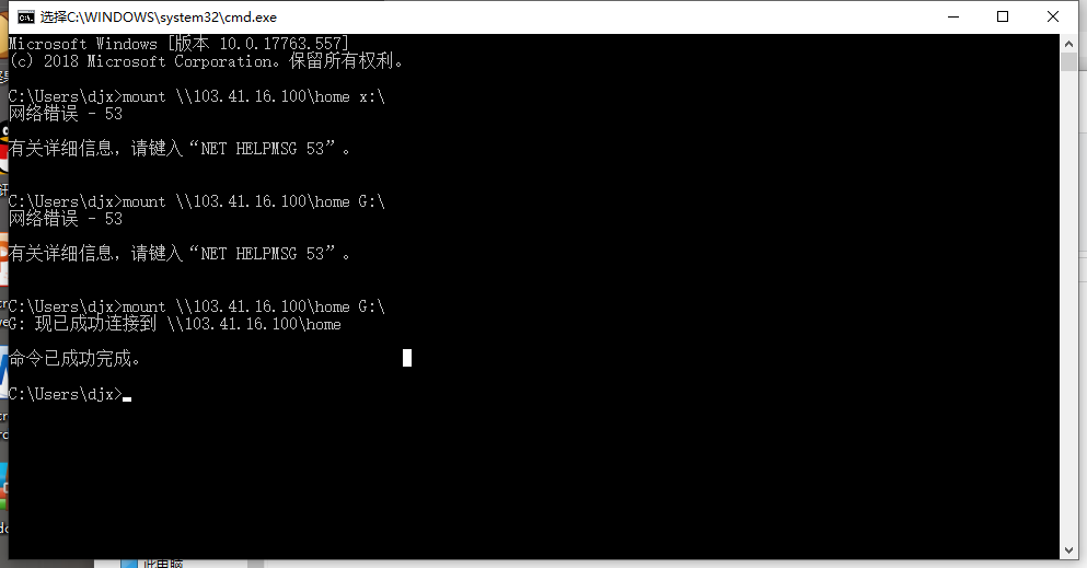
针对的是 windows 2008 server作为客户端mount的时候
如果我们设置为上面的内容后,发现连接的时候还是报 53的错误。我们可以进行下面的第二步设置。
在 配置文件 /etc/exports 设置读写权限的时候 设置参数 no_root_squash,不设置这个不行。
更改配置后需要重启 nfs server 。
systemctl start nfs-server
我们映射的目录权限最好为 777 ,否则可能访问不到。
客户端进行 mount 路径有误。 看下面示例:
例如映射的 目录是 /home ,那么 mount 的命令是 :
mount \\192.168.1.23\home X:\
例如映射的 目录是 /home/test ,那么 mount 的命令是 :
mount \\192.168.1.23\home/test X:\
注意多级目录后面就不是使用 \ 而是用 / 。
映射为本地的磁盘时,我们要选择我们没有使用的磁盘符。选用 X、Y、W等这些平常一般不使用的盘符号。
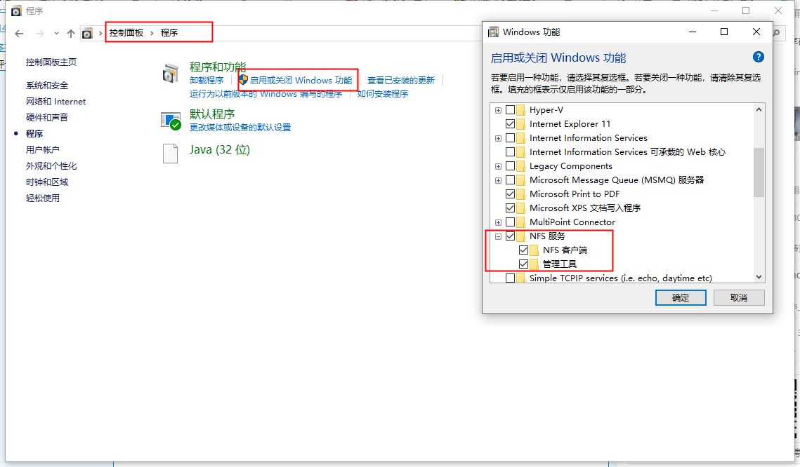
通过Server Manager,
1.添加角色,选中File Services,然后按照向导提示安装。
2.添加Features,安装Remote Server Administration Tools/Role Administration Tools/File Services Tool/Services for Network File System Tools
需要安装Services For Network File System
然后运行Services For Network File system,启动client for NFS
This page provides information on configuring telemetry on the router and the client for streaming and storing raw logs on an external linux machine.
telemetry model-driven
 destination-group telem_client

 ! Provide IP address and port on the machine where the collector is listening.
  address-family ipv4 10.65.44.195 port 57000
  encoding self-describing-gpb
  protocol tcp
 !
!
sensor-group my-servo
 sensor-path Cisco-IOS-XR-gnss-oper:gnss-receiver/nodes
 sensor-path Cisco-IOS-XR-ptp-oper:ptp/ptp-pd-oper:platform/servo
 sensor-path Cisco-IOS-XR-ptp-oper:ptp/ptp-pd-oper:platform/apr-log
 sensor-path Cisco-IOS-XR-ptp-oper:ptp/ptp-pd-oper:platform/servo-statistics
!

subscription servo-sub
 sensor-group-id my-servo sample-interval 5000
 destination-id telem_client
 source-interface MgmtEth0/RP0/CPU0/0
!
!
! Enable streaming of APR logs
ptp
 log
  servo driver
!
!
pipeline-gnmi as a collector for the telemetry client.
git clone https://github.com/cisco-ie/pipeline-gnmi.git
cd pipeline-gnmi
make build
Pipeline uses two configuration files:
- pipeline_cisco.conf
- metrics_cisco.json
[cisco-input]
stage = xport_input
type = tcp
encap = st
listen = : 57000      # Should be same as the port number configured in XR configuration

[mymetrics]
stage = xport_output
type = metrics
file = metrics_cisco.json    # Attached to this page
datachanneldepth = 1000
output = influx
influx = http://localhost:8086
database = ptp_db     # Influx database name used by pipeline for storing the received data
workers = 10
<pipeline-gnmi directory>/bin/pipeline_linux_amd64 --config pipeline_cisco.conf
wget https://dl.influxdata.com/influxdb/releases/influxdb_1.8.6_amd64.deb
sudo dpkg -i influxdb_1.8.6_amd64.deb
sudo service influxdb start
influx       # Enter influx database shell

# Create database which wraps around data after 8 hours
create database ptp_db with duration 8h       # Use same database name as specified in pipeline_cisco.conf file
influx     # Enter influx database shell
show databases      # List databases

use ptp_db             # Enter into a database

# List tables in the database
show measurements
Cisco-IOS-XR-gnss-oper:gnss-receiver/nodes/node/receivers/receiver
Cisco-IOS-XR-ptp-oper:ptp/Cisco-IOS-XR-ptp-pd-oper:platform/apr-log
Cisco-IOS-XR-ptp-oper:ptp/Cisco-IOS-XR-ptp-pd-oper:platform/servo
Cisco-IOS-XR-ptp-oper:ptp/Cisco-IOS-XR-ptp-pd-oper:platform/servo-statistics

# Show columns in a table
show field keys from "Cisco-IOS-XR-ptp-oper:ptp/Cisco-IOS-XR-ptp-pd-oper:platform/servo"
fieldKey fieldType
-------- ---------
lock-status integer
mean-path-delay integer
offset-from-master integer
phase-accuracy-last integer
servo-mode integer

#Retrieve data from the table
select "lock-status","offset-from-master" from "Cisco-IOS-XR-ptp-oper:ptp/Cisco-IOS-XR-ptp-pd-oper:platform/servo" order by desc limit 5
name: Cisco-IOS-XR-ptp-oper:ptp/Cisco-IOS-XR-ptp-pd-oper:platform/servo
time                lock-status offset-from-master
----                ----------- ------------------
1626669329152000000 2           2
1626669324152000000 2           2
1626669319153000000 2           2
1626669314152000000 2           2
1626669309152000000 2           2
sudo apt-get install -y adduser libfontconfig1
wget https://dl.grafana.com/oss/release/grafana_8.0.5_amd64.deb
sudo dpkg -i grafana_8.0.5_amd64.deb
sudo /bin/systemctl start grafana-server
Point the web-browser to http://<Ubuntu-VM-IP>:3000
Influx query language documentation: https://docs.influxdata.com/influxdb/v1.8/query_language/
This document provides some extra documentation and use cases on the use of port spanning or port mirroring.
You can monitor traffic passing in & out of a set of L2 or L3 Ethernet interfaces (including bundle-Ether).
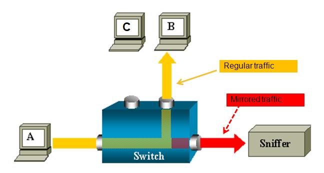
ASR 9000 is the only platform implementing SPAN on XR (Only support on ethernet linecards, not on SIP-700.)
You can use SPAN/Mirror in the follow scenarios
- L2 & L3 interfaces.
- Local, R-SPAN, and PW-SPAN only (no ER SPAN.)
- Scale limits:
8 monitor sessions
800 total source ports
1.5 Gig bidirectional replication limit toward fabric for bundle interfaces and 10 Gig ports.
Guideline: ~ 10% - 15% total bandwidth can be mirrored system-wide
- Source ports: Physical, EFPs, and bundles interfaces (L2 & L3)
- Destination ports: Ethernet interfaces, EFPs, and PW-SPAN. (No bundle) [ only L2 transport interfaces are supported as destination ports]
- Ability to use ACL's to define which traffic is to be captured
- Capture multicast traffic is possible
Note: some of the functionality mentioned are enhancements to the XR 4.0.1 release, this document assumes you are using this release or later.
A good reference on the terminology of SPAN/Mirror can be found here:
http://www.cisco.com/en/US/docs/switches/lan/catalyst6500/ios/12.2SX/configuration/guide/span.pdf
SPAN mirrors what is on the wire
For ingress, this means packets are mirrored before QOS, ACL, and encapsulation rewrite operations.
For egress, this means packets are mirrored after QOS, ACL, and encapsulation rewrite operations.
User can configure to mirror first 64 upto 256 bytes of the packet.
Note: The actual mirrored packet will be the configured size plus 4-byte trailling CRC.
Sample config:
interface GigabitEthernet0/6/0/20 l2transport
monitor-session PW
mirror first 100 <== valid range: [64, 256], inclusively
!
!
Note: The mirrored packet received at sniffer will have the size of 104
(4-byte of trailing CRC added by transmit MAC layer.)
“permit/deny” determines the behavior of the regular traffic (forwarded or dropped)
“capture” determines whether the packet is mirrored to the SPAN destination.
On SPAN: mirror traffic on the wire (regardless with or without ACL.)
ACL on ingress direction:
SPAN will mirror traffic even regular traffic dropped by ACL: Always mirror!
ACL on egress direction
Will mirror if regular traffic is forwarded (Permit)
Will not mirror if regular traffic is dropped (Deny.)
Inconsistent configurations:
“acl” is configured on SPAN source port but
ACL has no “capture” keyword:
No traffic gets mirrored.
“acl” is NOT configured on SPAN source port but
ACL has “capture” keyword:
Mirroring traffic as normal, no ACL performed.
The ACL can also be an L2 ACL :
ethernet-services access-list esacl_t2
10 deny 1234.5678.90ab 0000.0000.0000 any capture
monitor-session TEST
destination interface GigabitEthernet0/1/0/2 (<<<< this is NP3)
!
interface GigabitEthernet0/1/0/14 (<<<< this is NP2)
ipv4 address 5.5.1.1 255.255.255.0
monitor-session TEST
acl
!
load-interval 30
ipv4 access-group span ingress
!
ipv4 access-list span
10 permit ipv4 any host 1.1.1.10 capture
15 permit ipv4 any host 239.1.1.1 capture
20 permit ipv4 any host 2.2.2.100
30 permit ipv4 any any
Sample TRAFFIC GEN: (sending multicast in this example)
tgn rate 1000
L2-dest-addr 0100.5E01.0101
L2-src-addr 0003.A0FD.28A8
L3-src-addr 5.5.1.2
L3-dest-addr 239.1.1.1
Checking NP2: (the port that we are spanning)
Show global stats counters for NP2, revision v3
Read 12 non-zero NP counters:
Offset Counter FrameValue Rate (pps)
-------------------------------------------------------------------------------
22 PARSE_ENET_RECEIVE_CNT 5478 1001
31 PARSE_INGRESS_DROP_CNT 3 1
33 RESOLVE_INGRESS_DROP_CNT 5474 1000
(there is no mcast recipient for this mcast addr, but we’re still replicating, see red line)
40 PARSE_INGRESS_PUNT_CNT 1 0
50 MODIFY_RX_SPAN_CNT 5475 1000
54 MODIFY_FRAMES_PADDED_CNT 5475 1000
68 RESOLVE_INGRESS_L3_PUNT_CNT 1 0
104 LOOP 1 0
224 PUNT_STATISTICS 9 2
480 RESOLVE_IPM4_ING_RTE_DROP_CNT 5475 1000
565 UIDB_TCAM_MISS_AGG_DROP 3 1
570 UIDB_TCAM_MISS_PORT4_DROP_FOR_HOST 3 0
NP3 is the span monitor interface:
Show global stats counters for NP3, revision v3
Read 16 non-zero NP counters:
Offset Counter FrameValue Rate (pps)
-------------------------------------------------------------------------------
22 PARSE_ENET_RECEIVE_CNT 36 0
23 PARSE_FABRIC_RECEIVE_CNT 79656 1000
30 MODIFY_ENET_TRANSMIT_CNT 79655 1000
Packets received from fabric and sent off to the Ethernet on the span port!
For PW span to work, you need to define a local monitor session with a destination pseudo wire. You apply that span session to the interface of interest and define an xconnect group that also leverages that span session as one of the pw ends.
On the remote side where the PW terminates, you just configure regular VPWS.
Here an example:
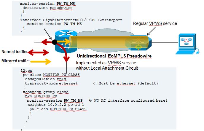
On the Local Side, besides my Span configuration, there is also a local cross connect between the interested session we want to span over the PW
l2vpn
xconnect group TEST
p2p TEST
interface GigabitEthernet0/1/0/39
! port 39 is the port where we apply the span on.
interface GigabitEthernet0/1/0/20.100
! this is just a random AC to have traffic flowing between the spanned port.
!
AC configuration:
interface GigabitEthernet0/1/0/20.100 l2transport
encapsulation dot1q 100
rewrite ingress tag pop 1 symmetric
! the tag is popped because the other XCON end is a plain ethernet without vlan. The explanation and use cases of tag popping can be found a related
! Tech note article.
Regular VPWS configuration:
RP/0/RSP0/CPU0:A9K-TOP#sh run l2vpn
l2vpn
xconnect group PW-SPAN
p2p PW-SPAN_1
interface GigabitEthernet0/0/0/39
neighbor 2.2.2.2 pw-id 1
!
!
!
interface GigabitEthernet0/0/0/39
load-interval 30
transceiver permit pid all
l2transport
!
!
the neighbor in the l2vpn configuration is the LDP neighbor ID
between which the PW is built.
Show on remote side:
RP/0/RSP0/CPU0:A9K-TOP#show l2vpn xcon group PW-SPAN det
Group PW-SPAN, XC PW-SPAN_1, state is up; Interworking none
AC: GigabitEthernet0/0/0/39, state is up
Type Ethernet
MTU 1500; XC ID 0x4000a; interworking none
Statistics:
packets: received 0, sent 16570475
bytes: received 0, sent 994228500
! packets received from the PW are sent out hte Attachment circuit's interface. The analyzer is connected to G0/0/0/39
PW: neighbor 2.2.2.2, PW ID 1000, state is up ( established )
PW class not set, XC ID 0x4000a
Encapsulation MPLS, protocol LDP
PW type Ethernet, control word disabled, interworking none
PW backup disable delay 0 sec
Sequencing not set
MPLS Local Remote
------------ ------------------------------ -----------------------------
Label 16002 16027
Group ID 0xa40 0x2
Interface GigabitEthernet0/0/0/39 PW/TM/MS
MTU 1500 1500
Control word disabled disabled
PW type Ethernet Ethernet
VCCV CV type 0x2 0x2
(LSP ping verification) (LSP ping verification)
VCCV CC type 0x6 0x6
(router alert label) (router alert label)
(TTL expiry) (TTL expiry)
------------ ------------------------------ -----------------------------
MIB cpwVcIndex: 4294705162
Create time: 04/04/2011 14:36:42 (00:20:07 ago)
Last time status changed: 04/04/2011 14:36:42 (00:20:07 ago)
Statistics:
packets: received 16570475, sent 0
bytes: received 994228500, sent 0
! Packets received on the Pseudo Wire from the SPAN port
NOTE: Pseudo Wire counters on the span side are not incrementing.That is the XCON group "cisco" in this picture config example.
This is intentional. You can review the SPANNING also with this command:
RP/0/RSP1/CPU0:A9K-BOTTOM#sh monitor-session counters
Monitor-session PW_TM_MS
GigabitEthernet0/1/0/39
Rx replicated: 58488205 packets, 3743245120 octets
Tx replicated: 58488206 packets, 3743245184 octets
Non-replicated: 0 packets, 0 octets
R-SPAN is natively support with the capability of ASR9000 to do vlan imposition:
monitor-session MS2
destination interface gig0/2/0/19.10
!
interface gig0/2/0/12.10 l2transport
encapsulation dot1q 10 <<< Monitoring vlan 10 traffic
monitor-session MS2
!
interface gig0/2/0/19.10 l2transport (*)
encapsulation dot1q 100 <<< VLAN 100 will get imposed.
!
(*) Monitor destination could be any supported destination interface regardless of monitor source
n/a
Xander Thuijs, CCIE #6775
Sr. Tech Lead ASR9000
https://community.cisco.com/t5/service-providers-documents/asr9000-xr-how-to-use-port-spanning-or-port-mirroring/ta-p/3108031