Saturday, December 11, 2021

ASR9000/XR: How to use Port Spanning or Port Mirroring


Introduction

This document provides some extra documentation and use cases on the use of port spanning or port mirroring.

You can monitor traffic passing in & out of a set of L2 or L3 Ethernet interfaces (including bundle-Ether).
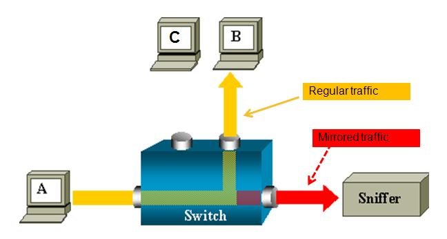
 

span1.JPG

Core Issue

ASR 9000 is the only platform implementing SPAN on XR (Only support on ethernet linecards, not on SIP-700.)


You can use SPAN/Mirror in the follow scenarios

- L2 & L3 interfaces.
- Local,  R-SPAN, and PW-SPAN only (no ER SPAN.)
- Scale limits:
    8 monitor sessions
    800 total source ports
    1.5 Gig bidirectional replication limit toward fabric for bundle interfaces and 10 Gig ports.
    Guideline:  ~ 10% - 15% total bandwidth can be mirrored system-wide
- Source ports:  Physical, EFPs, and bundles interfaces (L2 & L3)
- Destination ports:  Ethernet interfaces, EFPs, and PW-SPAN. (No bundle) [ only L2 transport interfaces are supported as destination ports]

- Ability to use ACL's to define which traffic is to be captured

- Capture multicast traffic is possible


Note: some of the functionality mentioned are enhancements to the XR 4.0.1 release, this document assumes you are using this release or later.


A good reference on the terminology of SPAN/Mirror can be found here:

http://www.cisco.com/en/US/docs/switches/lan/catalyst6500/ios/12.2SX/configuration/guide/span.pdf


SPAN order of operation

SPAN mirrors what is on the wire
For ingress, this means packets are mirrored before QOS, ACL, and encapsulation rewrite operations.
For egress, this means packets are mirrored after QOS, ACL, and encapsulation rewrite operations.


Partial Packet Mirroring

User can configure to mirror first 64 upto 256 bytes of the packet.
Note: The actual mirrored packet will be the configured size plus 4-byte trailling CRC.


Sample config:


interface GigabitEthernet0/6/0/20 l2transport
  monitor-session PW
  mirror first 100  <==  valid range: [64, 256], inclusively
  !
!


Note:  The mirrored packet received at sniffer will have the size of 104
               (4-byte of trailing CRC added by transmit MAC layer.)


ACL based Mirroring


“permit/deny” determines the behavior of the regular traffic (forwarded or dropped)
capture” determines whether the packet is mirrored to the SPAN destination.


On SPAN: mirror traffic on the wire (regardless with or without ACL.)

      ACL on ingress direction:
           SPAN will mirror traffic even regular traffic dropped by ACL:  Always mirror!
     ACL on egress direction
          Will mirror if regular traffic is forwarded (Permit)
          Will not mirror if regular traffic is dropped (Deny.)


Inconsistent configurations:
“acl” is configured on SPAN source port but
   ACL has no “capture” keyword:
    No traffic gets mirrored. 
“acl” is NOT configured on SPAN source port but
   ACL has “capture” keyword:
    Mirroring traffic as normal, no ACL performed.


The ACL can also be an L2 ACL :


ethernet-services access-list esacl_t2
10 deny 1234.5678.90ab 0000.0000.0000 any capture


L3 Spanning Example


monitor-session TEST
destination interface GigabitEthernet0/1/0/2 (<<<< this is NP3)
!
interface GigabitEthernet0/1/0/14  (<<<< this is NP2)
ipv4 address 5.5.1.1 255.255.255.0
monitor-session TEST
  acl
!
load-interval 30
ipv4 access-group span ingress
!
ipv4 access-list span
10 permit ipv4 any host 1.1.1.10 capture
15 permit ipv4 any host 239.1.1.1 capture
20 permit ipv4 any host 2.2.2.100
30 permit ipv4 any any


Sample TRAFFIC GEN: (sending multicast in this example)
tgn rate 1000
L2-dest-addr 0100.5E01.0101
L2-src-addr 0003.A0FD.28A8
L3-src-addr 5.5.1.2
L3-dest-addr 239.1.1.1


Checking NP2(the port that we are spanning)
Show global stats counters for NP2, revision v3


Read 12 non-zero NP counters:
Offset  Counter                                         FrameValue   Rate (pps)
-------------------------------------------------------------------------------
  22  PARSE_ENET_RECEIVE_CNT                                  5478        1001
  31  PARSE_INGRESS_DROP_CNT                                     3           1
  33  RESOLVE_INGRESS_DROP_CNT                                5474        1000
(there is no mcast recipient for this mcast addr, but we’re still replicating, see red line)
  40  PARSE_INGRESS_PUNT_CNT                                     1           0
  50  MODIFY_RX_SPAN_CNT                                      5475        1000
  54  MODIFY_FRAMES_PADDED_CNT                                5475        1000
  68  RESOLVE_INGRESS_L3_PUNT_CNT                                1           0
104  LOOP                                                       1           0
224  PUNT_STATISTICS                                            9           2
480  RESOLVE_IPM4_ING_RTE_DROP_CNT                           5475        1000
565  UIDB_TCAM_MISS_AGG_DROP                                    3           1
570  UIDB_TCAM_MISS_PORT4_DROP_FOR_HOST                         3           0


NP3 is the span monitor interface:
Show global stats counters for NP3, revision v3


Read 16 non-zero NP counters:
Offset  Counter                                         FrameValue   Rate (pps)
-------------------------------------------------------------------------------
  22  PARSE_ENET_RECEIVE_CNT                                    36           0
  23  PARSE_FABRIC_RECEIVE_CNT                               79656        1000
  30  MODIFY_ENET_TRANSMIT_CNT                               79655        1000


Packets received from fabric and sent off to the Ethernet on the span port!


PW SPAN example

For PW span to work, you need to define a local monitor session with a destination pseudo wire. You apply that span session to the interface of interest and define an xconnect group that also leverages that span session as one of the pw ends.


On the remote side where the PW terminates, you just configure regular VPWS.

Here an example:
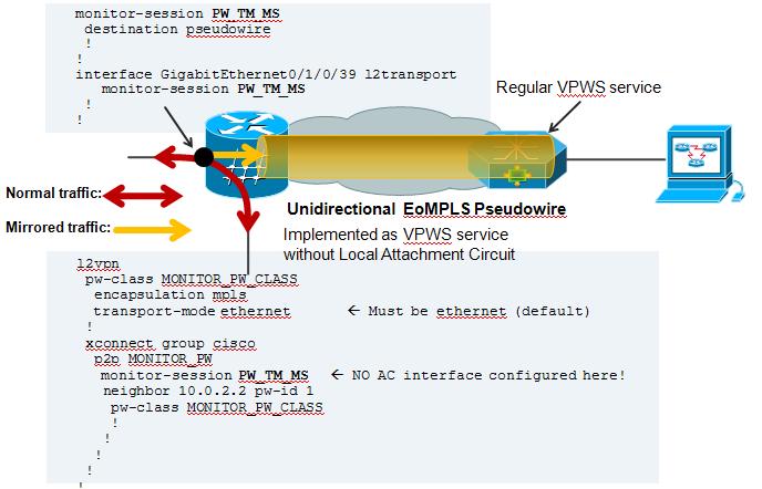
 

pw-span.JPG


On the Local Side, besides my Span configuration, there is also a local cross connect between the interested session we want to span over the PW


l2vpn

xconnect group TEST
  p2p TEST
   interface GigabitEthernet0/1/0/39

   ! port 39 is the port where we apply the span on.
   interface GigabitEthernet0/1/0/20.100
  ! this is just a random AC to have traffic flowing between the spanned port.
!


AC configuration:

interface GigabitEthernet0/1/0/20.100 l2transport
encapsulation dot1q 100
rewrite ingress tag pop 1 symmetric
! the tag is popped because the other XCON end is a plain ethernet without vlan. The explanation and use cases of tag popping can be found a related

! Tech note article.


Configuration on the remote side:


Regular VPWS configuration:


RP/0/RSP0/CPU0:A9K-TOP#sh run l2vpn
l2vpn
xconnect group PW-SPAN
  p2p PW-SPAN_1
   interface GigabitEthernet0/0/0/39
   neighbor 2.2.2.2 pw-id 1
   !
  !
!
interface GigabitEthernet0/0/0/39
load-interval 30
transceiver permit pid all
l2transport
!
!


the neighbor in the l2vpn configuration is the LDP neighbor ID
between which the PW is built.


Show on remote side:
RP/0/RSP0/CPU0:A9K-TOP#show l2vpn xcon group PW-SPAN det


Group PW-SPAN, XC PW-SPAN_1, state is up; Interworking none
  AC: GigabitEthernet0/0/0/39, state is up
    Type Ethernet
    MTU 1500; XC ID 0x4000a; interworking none
    Statistics:
      packets: received 0, sent 16570475
      bytes: received 0, sent 994228500

! packets received from the PW are sent out hte Attachment circuit's interface. The analyzer is connected to G0/0/0/39
  PW: neighbor 2.2.2.2, PW ID 1000, state is up ( established )
    PW class not set, XC ID 0x4000a
    Encapsulation MPLS, protocol LDP
    PW type Ethernet, control word disabled, interworking none
    PW backup disable delay 0 sec
    Sequencing not set


      MPLS         Local                          Remote
      ------------ ------------------------------ -----------------------------
      Label        16002                          16027
      Group ID     0xa40                          0x2
      Interface    GigabitEthernet0/0/0/39        PW/TM/MS
      MTU          1500                           1500
      Control word disabled                       disabled
      PW type      Ethernet                       Ethernet
      VCCV CV type 0x2                            0x2
                   (LSP ping verification)        (LSP ping verification)
      VCCV CC type 0x6                            0x6
                   (router alert label)           (router alert label)
                   (TTL expiry)                   (TTL expiry)
      ------------ ------------------------------ -----------------------------
    MIB cpwVcIndex: 4294705162
    Create time: 04/04/2011 14:36:42 (00:20:07 ago)
    Last time status changed: 04/04/2011 14:36:42 (00:20:07 ago)
    Statistics:
      packets: received 16570475, sent 0
      bytes: received 994228500, sent 0

! Packets received on the Pseudo Wire from the SPAN port


NOTE: Pseudo Wire counters on the span side are not incrementing.That is the XCON group "cisco" in this picture config example.

This is intentional. You can review the SPANNING also with this command:


RP/0/RSP1/CPU0:A9K-BOTTOM#sh monitor-session counters

Monitor-session PW_TM_MS
  GigabitEthernet0/1/0/39
    Rx replicated: 58488205 packets, 3743245120 octets
    Tx replicated: 58488206 packets, 3743245184 octets
    Non-replicated: 0 packets, 0 octets


R-SPAN configuration:

R-SPAN is natively support with the capability of ASR9000 to do vlan imposition:


monitor-session MS2

destination interface gig0/2/0/19.10

!

interface gig0/2/0/12.10 l2transport

encapsulation dot1q 10 <<< Monitoring vlan 10 traffic

monitor-session MS2

!

interface gig0/2/0/19.10 l2transport (*)

encapsulation dot1q 100 <<< VLAN 100 will get imposed.

!


(*) Monitor destination could be any supported destination interface regardless of monitor source


Related Information

n/a


Xander Thuijs, CCIE #6775

Sr. Tech Lead ASR9000


https://community.cisco.com/t5/service-providers-documents/asr9000-xr-how-to-use-port-spanning-or-port-mirroring/ta-p/3108031

Support of: unhide viptela_internal


Introduction


Starting 20.4 release, we have removed the support for unhide viptela_internal command which let (TAC) Engineers troubleshoot the customer issues.    unhide viptela_internal is no longer a valid command and any of the previously hidden commands that remain for field, use are either “support” commands, are have been made fully supported commands.   


Background


There are MANY hidden commands.  If you go to a Viptela device CLI you will not see “show internal” or “request internal” or “tools internal”.  But if you type “unhide viptela_internal” and then provide the password ”  ", you will then be able to see those.  And underneath them are many more commands, all usually hidden and none of them are documented.  This is considered a security violation under Cisco rules.  Because this is not documented, it is considered a back door.  Because there is a password, it appears to be a more serious back door.  And this password has been posted (by others) online. 


Also note, in 19.2.3, 20.1.2. 20.3.1 and 20.3.2, we no longer user "unhite viptela_internal" to access.   Instead, use "unhide full".  The password is the same as used with viptela_internal.  See CSCvt00497  for more information.


With CSCwa45995: We are removing all traces of "unhide viptela internal" from the cEdge platform.   As part of removing hidden config (which could be exposed via unhide command), some commands were missed on polaris.  With this CDETS, we will be removing all instances of "viptela_internal" hidegroup from the code.  


External Notification


The following CCO link is posted externally.  

For the reasons mentioned above, the password and the list of hidden commands are published in below link.


https://www.cisco.com/c/dam/en/us/td/docs/routers/sdwan/Internal-Commands/Troubleshooting-Commands-f...


20.4 and after


vEdge# unhide viptela_internal
Error: unknown hide group


Any of the previously hidden commands that remain for field use, are moved under the support option 

There may be some commands that could be missing.     See below for more information.


vEdge# tools support ?
Possible completions:
  fp-dump   Perform fp-dump on a network interface
vEdge#


vEdge# show support ?     
Possible completions:
  cellular       cellular support commands
  cloudexpress   cloudexpress support commands
  control        DTLS support shell commands
  dhcp           DHCP support commands
  dnsd           dnsd support commands
  dpi            dpi support commands
  filter         filter support commands
  fp             Fast-path support commands
  ftm            ftm support commands
  nat            nat support commands
  omp            OMP support commands
  pim            pim support commands
  resolv         resolvd support commands
  tracker        tracker support commands
  ttm            TTM support commands
  vrrp           VRRP support commands
vEdge#


vEdge# request support ?
Possible completions:
  cellular               
  debug-malloc           Malloc-trim in a daemon
  fp                     
  router-advertisement   Enable/Disable Ipv6 Router Advertisements tx/rx interface
  software               
  tcpopt                 
  vdebug                 Control vdebug RAM disk logging
vEdge#


For UnPinning of flows on vE2K

vEdge# request support fp unpin-flows


Moving the deivce to vManaged mode or not

Currently there is no option to move the device in or out of vManage mode.  This option is not directly available to the customer.  It requires the use of 'unhide viptela_internal', and then from config mode running 'no system is-vmanaged'.

In 20.4, this is missing.     CSCvx23574  is opened to track this.   This will address for both cEdge and vEdge platforms.


Capturing (existing) Internal commands


Below are the tools, show and request internal commands as taken from 20.3.1 node.


show internal


vEdge# show  internal ?
Possible completions:
  admin-tech     Admin-tech commands
  app-route      
  cellular       
  cfgmgr         Configuration Manager shell commands
  cflowd         
  cloudexpress   cloudexpress commands
  control        DTLS shell commands
  cxp-app        
  dbgd           
  dhcp           DHCP shell commands
  dnsd           dnsd commands
  dot1x          
  dpi            dpi commands
  filter         
  flow-db        Flow Database
  flow-summary   Flow Database Summary
  fp             Fast-path shell commands
  fpm            
  ftm            
  gps            
  igmp           
  nat            
  omp            OMP shell commands
  pim            
  policy         Policy shell commands
  resolv         
  rtm            RTM shell commands
  server-app     
  snmp           SNMP shell commands
  sysmgr         
  system         
  tcpopt-db      
  tcpopt-tcpd    
  tracker        Tracker shell commands
  ttm            TTM shell commands
  tunnel         
  vrrp           VRRP shell commands
  wlan           
  zbf            
vEdge#


request internal


vEdge# request internal ?
Possible completions:
  cloudexpress      Cloudexpress related tools command
  embargo           vEdge embargo check
  fec               
  fp-dump           Perform fp-dump on a network interface
  ftm               
  interface-reset   
  live-core         Generate non-disruptive coredump of a running process
  malloc-trim       Malloc-trim in a daemon
  reset             Reset system or logs
  software          
  tcpopt            
  vdebug            Control vdebug RAM disk logging
  vedge-cloud       vEdge cloud internal commands
vEdge#


tools internal


vEdge# tools internal ?
Possible completions:
  clean_db            Remove vManage data
  csr_read            Reading cavium registers.
  csr_write           Writing into cavium registers.
  ethtool             ethtool
  firmware-printenv   Display environment variables.
  fp-dump             Perform fp-dump on a network interface
  hostapd_cli         hostapd_cli
  i2cdetect           i2cdetect tool.(Only for Mips)
  i2cdump             i2cdump tool.
  i2cget              i2cget tool. (only for Mips)
  i2cset              i2cset tool.
  mdio-read           mdio-read
  mdio-write          mdio-write
  mii-tool            mii-tool
  oui-lookup          Perform OUI lookup for show arp.
  poe-tool            poe-tool
  process_id          Find process ID.
  remove_tenancy      Remove Tenancy file on vManage
  tlv_tool            TLV tool.(Only for Mips)
  touch_test_root     Create or remove /usr/share/viptela/test_root for allowing any root cert for sw vedges.
  tracker             Add Latency on the interface for tracker packets
  valgrind_tool       Enable valgrind on a process.
vEdge#


Troubleshooting SD-WAN cEdge IPsec Replay Failures


Introduction


IPsec authentication provides built-in anti-replay protection against old or duplicated IPsec packets by checking the sequence number in the ESP header on the receiver. Anti-replay packet drops is one of the most common data-plane issues with IPsec due to packets delivered out of order outside of the anti-replay window. A general troubleshooting approach for IPsec anti-replay drops can be found here, and general technique applies to SDWAN as well. However, there are some implementation differences between traditional IPsec and IPsec used in the Cisco SD-WAN solution. This article is intended to explain these differences and the troubleshooting approach on the cEdge platforms running IOS-XE.


SDWAN Replay Detection Considerations


Group key vs. Pairwise key


Unlike traditional IPsec, where IPsec SAs are negotiated between two peers using the IKE protocol, SDWAN uses a group key concept. In this model, an SDWAN edge device periodically generates data plane inbound SA per TLOC and send these SAs to the vSmart controller, which in turn propagates the SA to the rest of the edges devices in the SD-WAN network. For a more detailed description of the SD-WAN data plane operations, see SD-WAN Data Plane Security Overview.


Note: Starting from IOS-XE 16.12.1a/SD-WAN 19.2, IPsec pairwise keys are supported. See IPsec Pairwise Keys Overview. With Pairwise keys, IPsec anti-replay protection works exactly like traditional IPsec. This article primarily will focus on replay check using the group key model.


SPI Encoding


In the IPsec ESP header, the SPI (Security Parameter Index) is a 32 bit value that the receiver uses to identify the SA to which an incoming packet should be decrypted with. With SD-WAN, this inbound SPI can be identified with show crypto ipsec sa:


cedge-2#show crypto ipsec sa | se inbound
     inbound esp sas:
      spi: 0x123(291)
        transform: esp-gcm 256 ,
        in use settings ={Transport UDP-Encaps, esn}
        conn id: 2083, flow_id: CSR:83, sibling_flags FFFFFFFF80000008, crypto map: Tunnel1-vesen-head-0
        sa timing: remaining key lifetime 9410 days, 4 hours, 6 mins
        Kilobyte Volume Rekey has been disabled
        IV size: 8 bytes
        replay detection support: Y
        Status: ACTIVE(ACTIVE)

Note: The SPI displayed with this command may not be the actual SA used in the data plane due to CSCvt06182 .


Notice even though this inbound SPI is the same for all the tunnels, the receiver has a different SA and the corresponding replay-window object associated with the SA for each peer edge device since the SA is identified by the source, destination ip address, source, destination ports 4-tuple, and the SPI number. So essentially, each peer will have its own anti-replay window object.


When looking at the actual packet sent by the peer device, one may notice the SPI value is different from the above output. Here is an example from the packet-trace output with the packet copy option enabled:


Packet Copy In
  45000102 0cc64000 ff111c5e ac127cd0 ac127cd1 3062303a 00eea51b 04000123
  00000138 78014444 f40d7445 3308bf7a e2c2d4a3 73f05304 546871af 8d4e6b9f

The actual SPI in the ESP header is 0x04000123. The reason for this is that, the leading bits in the SPI for SD-WAN are encoded with additional information, and only the low bits of the SPI field are allocated for the actual SPI. 


Traditional IPsec:


 0                   1                   2                   3
 0 1 2 3 4 5 6 7 8 9 0 1 2 3 4 5 6 7 8 9 0 1 2 3 4 5 6 7 8 9 0 1
+-+-+-+-+-+-+-+-+-+-+-+-+-+-+-+-+-+-+-+-+-+-+-+-+-+-+-+-+-+-+-+-+
|               Security Parameters Index (SPI)                 | 
+-+-+-+-+-+-+-+-+-+-+-+-+-+-+-+-+-+-+-+-+-+-+-+-+-+-+-+-+-+-+-+-+ 

SD-WAN:


 0                   1                   2                   3
 0 1 2 3 4 5 6 7 8 9 0 1 2 3 4 5 6 7 8 9 0 1 2 3 4 5 6 7 8 9 0 1
+-+-+-+-+-+-+-+-+-+-+-+-+-+-+-+-+-+-+-+-+-+-+-+-+-+-+-+-+-+-+-+-+ 
|  CTR  | MSNS|         Security Parameters Index (SPI)         | 
+-+-+-+-+-+-+-+-+-+-+-+-+-+-+-+-+-+-+-+-+-+-+-+-+-+-+-+-+-+-+-+-+ 

Where:


  • CTR (first 4 bits, bits 0-3) - Control Bits, used to indicate specific type of control packets. For example control bit 0x80000000 is used for BFD.
  • MSNS (next 3 bits, bits 4-6) - Multiple Sequence Number Space Index. This is used to locate the correct sequence counter in the sequence counter array to check for replay for the given packet. For SD-WAN, the 3 bit of MSNS allows for 8 different traffic classes to be mapped into their own sequence number space. This implies the effective SPI value that can be used for SA selection is the reduced low order 25 bits from the full 32 bit value of the field. More on this below.


Multiple Sequence Number Space for QoS


It is common to observe IPsec replay failures in an environment where packets are delivered out of order due to QoS, e.g., LLQ, since QoS is always run after IPsec encryption and encapsulation. The Multiple Sequence Number Space solution solves this problem by maintaining multiple sequence number spaces mapped to different QoS traffic classes for a given Security Association. The different sequence number space is indexed by the MSNS bits encoded in the ESP packet SPI field as depicted above. For a more detailed description, please see IPsec Anti Replay Mechanism for QoS


As noted above, this Multiple Sequence Number implementation implies the effective SPI value that can be used for SA selection is the reduced low order 25 bits. Another practical consideration when configuring the replay window size with this implementation is that, the configured replay-window size is for the aggregate replay window, so the effective replay window size for each Sequenc Number Space is 1/8 of the aggregate. For example, with the following configuration:


config-t
Security
ipsec
replay-window 1024
Commit


The effective replay window size for each Sequence Number Space is 1024/8 = 128!


Note: starting from IOS-XE 17.2.1, the aggregate replay window size has been increased to 8192 so that each Sequence Number Space can have a maximum replay window of 8192/8 = 1024 packets. This change was introduced with CSCvs51630 .


On an IOS-XE cEdge device, the last sequence number received for each requence number space can be obtained from the following IPsec dataplane output:


cedge-2#show crypto ipsec sa peer 172.18.124.208 platform

<snip>

------------------ show platform hardware qfp active feature ipsec datapath crypto-sa 5 ------------------

 Crypto Context Handle: ea54f530
 peer sa handle: 0
 anti-replay enabled
 esn enabled
 Inbound SA
 Total SNS: 8
 Space                highest ar number
 ----------------------------------------
   0                               39444
   1                                   0
   2                                1355
   3                                   0
   4                                   0
   5                                   0
   6                                   0
   7                                   0
<snip>

In the above example, the highest anti-replay window (Right edge of the anti-replay sliding window) for MSNS of 0 (0x00) is 39444, and that for MSNS of 2 (0x04) is 1335, and these counters will be used to check if the sequence number is inside of the replay window for packets in the same sequence number space.


Note: There are implementation differences betweem the ASR1k platform and the rest of the IOS-XE routing platforms (ISR4k, ISR1k, CSR1kv). As a result, there are some discrepancies in terms of the show commands and their output for these platforms. Currently, there is no command that will display the inbound top replay window edge on the ASR1k platform. This will hopefully be addressed in 17.3 as part of our serviceability effort.


Troubleshooting Replay Drop Failures


Troubleshooting Data Collection


When dealing with IPsec anti-replay drops, it's important to understand the conditions and potential triggers of the problem. At a minimum, collect the following set of information for to provide the context:


  • Device information for both the sender and receiver for the replay packet drops, including type of device, cEdge vs. vEdge, software version, and configuration.
  • Problem history. How long has the deployment been in place? How long has the problem been happening? Any recent changes to the network or traffic conditions.
  • Any pattern to the replay drops, e.g., is it sporadic or constant? Time of the problem and/or significant event, e.g., does it only happen during high traffic peak production hours, or only during rekey, etc.?


With the above information collected, proceed with the following troubleshooting workflow.


Troubleshooting workflow


The general troubleshooting approach for IPsec replay issues is just like how it's performed for traditional IPsec, while taking into account the per-peer SA sequence space and Multiple Sequence Number Space as explained above. Then follow these steps:


1. First identify the peer for the replay drop from the syslog and the drop rate. For drop statistics, always collect multiple timestamped snapshots of the output so that the drop rate can be quatified:


*Feb 19 21:28:25.006: %IOSXE-3-PLATFORM: R0/0: cpp_cp: QFP:0.0 Thread:000 TS:00001141238701410779 %IPSEC-3-REPLAY_ERROR: IPSec SA receives anti-replay error, DP Handle 6, src_addr 172.18.124.208, dest_addr 172.18.124.209, SPI 0x123

cedge-2#show platform hardware qfp active feature ipsec datapath drops
Load for five secs: 1%/0%; one minute: 1%; five minutes: 1%
No time source, *11:25:53.524 EDT Wed Feb 26 2020
------------------------------------------------------------------------
Drop Type  Name                                     Packets
------------------------------------------------------------------------
        4  IN_US_V4_PKT_SA_NOT_FOUND_SPI                              30
       19  IN_CD_SW_IPSEC_ANTI_REPLAY_FAIL                            41

It's not uncommon to see occasional replay drops due to packet delivery reordering in the network, but persistent replay drops that's service impacting should be investigated.


2a. For relatively low traffic rate, take a packet-trace using a condition set to be the peer ipv4 address with the copy packet option and examine the sequence numbers for the packet dropped against the current replay window right edge and sequence numbers in the adjacent packets to confirm if they are indeed duplicate or outside of the replay window.


2b. For high traffic rate with no predictable trigger, setup an EPC capture using circular buffer and EEM to stop the capture when replay errors are detected. Since EEM is currently not supported on vManage as of 19.3, this implies the cEdge would have to be in CLI mode when this troubleshooting task is performed. Once the capture is taken, use the BDB IPsec replay analyzer to analyze the packet capture for replay conditions.


3. Collect the show crypto ipsec sa peer x.x.x.x platform on the receiver ideally at the same time the packet capture or packet-trace is collected. This command should include the realtime dataplane replay window information for both the inbound and outbound SA.


4. If the packet dropped is indeed out of order, then take simultaneous captures from both the sender and receiver to identify if the problem is with the source or with the underlay network delivery layer.


5. If the packets are dropped even though they are neither duplicate nor outside of the replay window, then it's usually indicative of a software problem on the receiver.


Known Issues/Enhancements


  • CSCvq31153  SDWAN BFD session stuck and packet drops due to IN_CD_SW_IPSEC_ANTI_REPLAY_FAIL drops
  • CSCvr64231  BFD down with IPSec SA receives anti-replay error after NAT session flap sometimes
  • CSCvs48535  %IPSEC-3-REPLAY_ERROR: + BFD down and drops IN_CD_COPROC_ANTI_REPLAY_FAIL (vEdge incorrectly resets ESP seq.)
  • CSCvn79788  Incorrect syslog for anti-replay error on TSN1100 platform with SDWAN per-Tunnel QoS
  • CSCvs51630  cEdge: 'security ipsec replay-window' needs to support 8192
  • CSCvq75871 : SDWAN ipsec anti-replay drops for all packets when NAT session flap
  • CSCvn67507 : Packet drops due to IPSec-input and anti-replay when remote TLOC flaps
  • CSCvx15750 : SD-WAN:cEdge ipsec replay-window size decreases to 128 after a peer reloading
  • CSCvr64231 : BFD down with IPSec SA receives anti-replay error after NAT session flap sometimes
  • CSCvw00044 : 20.4-EFT: BFD sessions down on vEdge due to rx_replay_integrity_drops - Polaris side commit
  • CSCvs98389 : Packet drops in XE-SDWAN because of "IN_CD_COPROC_ANTI_REPLAY_FAIL" errors


References