Data Center Interconnects (DCI) products are targeted at the Edge or Border leaf of Data Center environments, joining Data Centers to each other in a Point-to-Point or Point-to-Multipoint fashion, or at times extending the connectivity to Internet Gateways or peering points. Cisco has two converged DCI solutions; one is with integrated DWDM and another with advanced L3 routing and L2 switching technologies. A recent Dell’Oro report, forecasts the aggregate sales of equipment for DCI will grow by 85 percent over the next five years. This is driving strong demand for Ethernet Data Center Switch, and Routing technologies.
The emerging need for simplified DCI offering spans four core markets.
· Mega Scale DC
· Cloud DC
· Telco Cloud
· Large Enterprises
The emergence of cloud computing has seen a rush of traffic being centralized in regional and global data center as the Data Center emergence to being the core of many service deliveries, more recently ‘far edge’ compute in 5G has reemphasized the trend, with DC’s now being at the core of 5G build outs, as Web companies and SPs embark on using automation and modern DC tools to turn up 5G sites at unprecedent rates and look at micro data centers at the edge to enhance the user experience.
DCI’s newest architectures is drive by massive DCs that need connecting by either leased lines from SPs or by deploying their own or leasing dark fiber.
Inside the DC they often deploy a mix of their home-grown applications over and defined technologies, mostly L2 type services to reach compute hosts at the peripherals, although we have seen recent trends of L3 being expended all the way to compute with Segment Routing (SR).
Outside the DC fiber is less abundant and inter DC solutions are fairly standardized with SP class products providing the richest functionality at the most optimal scale and price point. A motivation in the last 2 years for further DCI upgrades has been the migrating to MacSec for Inter DCI links.
A most recent trend is of 100GE and 400GE Data center build outs, driving DCI upgrades, we’re seeing customers migrate to higher speed links at different inflection points, with 100GE being the sweet spot current, creating catalyst for Terabit platforms that support advanced L2/L3 VPN services and Route and Bridge functions, case in point ASR9000 and NCS5500.
2. ASR 9000 L2 DCI GW feature overview
Ethernet VPN (EVPN) and Virtual Extensible LAN (VXLAN) have become very popular technologies for Data Center (DC) fabric solution. EVPN is used as a control plane for the VXLAN-based fabric and provides MAC addresses advertisements via MP-BGP. It eliminates the use of the flood and learn approach of original VXLAN standard (RFC7348.) As a result, DC fabric allows to reduce unwanted flooding traffic, increase load sharing, provide faster convergence and detection of link/device failures, and simplify DC automation.
ASR9k as a feature reach platform can be used in DC fabric as a DC edge router. With one leg in DC and other in WAN, ASR9k is the gateway for traffic leaving/entering DC. At DC fabric facing, ASR9k operates as border leaf. At MPLS WAN facing, ASR9k operates as WAN edge PE. Such type of router is commonly referred to as DC Interconnect (DCI) Gateway router or EVPN-VXLAN L2/L3 gateway.
There are two main use-cases that are widely known in the industry: L3 DCI gateway as a solution for L3VPN service on VXLAN fabric and L2-based gateway which provides L2 stitching between VXLAN fabric and MPLS -based Core.
The first use-case was available in XR release 5.3.2. It was the 1st phase of ASR9K based DCI GW solution
In phase 2, beginning from 6.1.1 release, EVPN Route Type 2 (MAC route) was integrated with L2 MAC learning/forwarding on the data plane. This functionality is called EVPN-VXLAN L2 gateway. Multicast routing was used as an underlay option for distribution of BUM (Broadcast, Unknown unicast, Multicast) traffic within VXLAN Fabric. Starting from release 6.3.1 ASR9K-based DCI solution supports Ingress Replication underlay capability on the VXLAN fabric side.
EVPN-VXLAN L2 gateway functionality will be described in the following sections.
The reference topology for this solution is shown at the picture below.
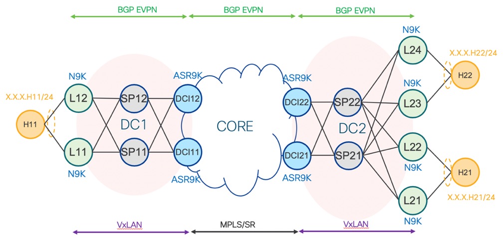
Nexus 9000 plays role of ToR/Leaf switches for this DCI solution. N9K ToRs should provide Per-VLAN first-hop L3 GW for Hosts/VMs behind the ToRs.
ASR9K DCI GW acts as an L2 EVPN-VXLAN GW within the fabric and participates in fabric-side EVPN control plane to learn local fabric MAC routes advertised from ToRs, and distribute external MAC routes learnt from remote DCI GWs, towards the ToRs. VXLAN data plane is used within the fabric. Fabric side BGP-EVPN sessions between DCI GWs and ToRs can be eBGP or iBGP.
On the core side, DCI GW will do BGP-EVPN peering with remote DCI GWs to exchange MAC routes together with host IP bindings (needed for ARP suppression on the ToRs). MPLS data plane is used on the core side. Core side BGP-EVPN session can be eBGP or iBGP as well.
On the WAN or external core side, ASR9K DCI GW acts as an L2 EVPN-MPLS GW that participates in EVPN control plane with remote DCI GWs to learn external MAC routes from them and distribute fabric MAC routes, learnt locally towards them. MPLS data plane is used with remote PODs, outside the fabric. In essence, the L2 DCI GW stitches the fabric side and WAN side EVPN control planes and in data plane, it bridges traffic between VXLAN tunnel bridge-port and MPLS tunnel bridge-port.
2.1. Distribution of BUM traffic
In DC switching network, L2 BUM traffic flooding between leaf nodes (including border leaf on DCI GW) is necessary. There are 2 operational modes for BUM traffic forwarding. The first mode is called egress replication. In this mode, the VXLAN underlay is capable of both L3 unicast and multicast routing. L2 BUM traffic is forwarded using underlay multicast tree. Packet replication is done by L3 IP multicast - an egress replication scheme.
The second mode of operation is called VXLAN Ingress Replication (VXLAN IR). This mode is used when VXLAN underlay transport network is not capable of L3 multicasting. In this mode, the VXLAN imposition node maintains a per VNI list of remote VTEP nodes which service the same tenant VNI. The imposition node replicates BUM traffic for each remote VTEP node. Each copy of VXLAN packet is sent to destination VTEP by underlay L3 unicast transport.
3. Multihoming deployment models
Depending on the capability of ToRs, ASR 9000 DCI supports two multi-homing deployment models
Anycast VXLAN L2 GW model
ESI based multi-homing VXLAN GW model
These models are based on different mechanisms inside DC fabric for multi-homing and load-balancing between ToRs and DCI GWs. On the MPLS WAN side both models use the same implementation approach.
3.1. Anycast VXLAN L2 Gateway
DC gateway redundancy and load sharing is a critical requirement for modern high-scalable data centers. Today, in every new DC deployment, multi-homing DCI gateway is a must-have requirement. Anycast VXLAN gateway is a simple approach of multi-homing. It requires multi-homing gateway nodes to use a common VTEP IP. Gateway nodes in the same DC advertise the common VTEP IP in all EVPN routes from type 2 to 5. N9k ToR nodes in the DC see one DCI GW VTEP located on multiple physical gateway nodes. Each N9k forwards traffic to the closest gateway node via IGP routing. Closest gateway is identified by shortest distance metric or ECMP algorithm.
Among multi-homing DCI gateway nodes, an EVPN Ethernet Segment is created on VXLAN facing interface NVE. One of the nodes is elected as DF for a tenant VNI. The DF node is responsible for flooding BUM traffic from Core to DC.
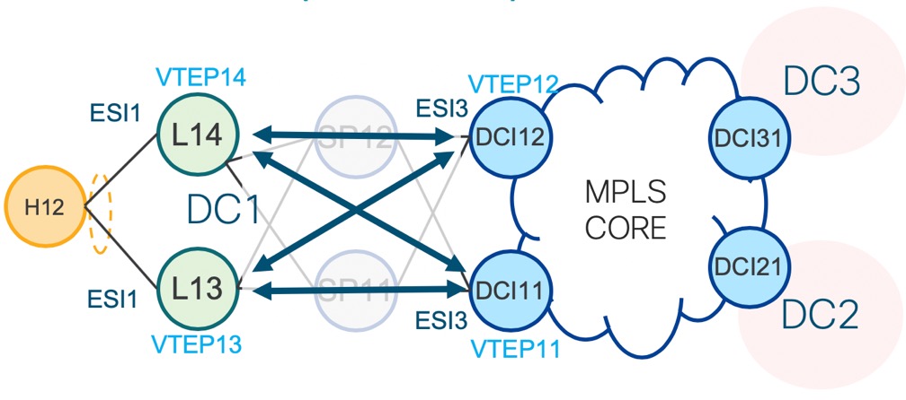
All DCI GW/PE nodes discover each other via EVPN routes advertised at WAN. EVPN L2 tunnels are fully meshed between DCI PE nodes attach to MPLS Core. See at the blue lines on the picture below.
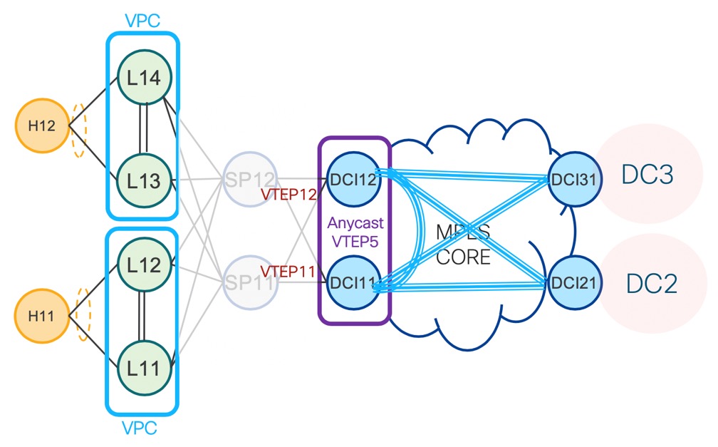
This picture describes a topology of anycast VXLAN gateway between DC and Core. In this topology, both ASR9k DCI GW nodes share a source VTEP IP address. N9k runs vPC mode in pairs.
Redundant DCI GWs use anycast VTEP loopback to advertise towards the VXLAN fabric. This loopback IP is used by ToR to forward traffic to DCI GW.
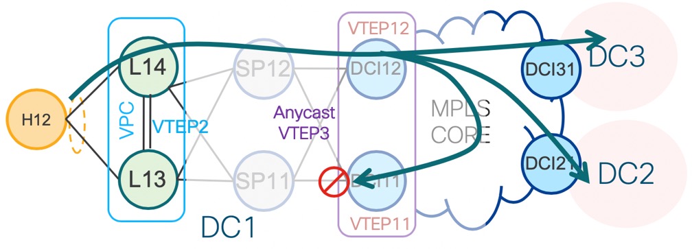
In the pictures below the BUM traffic distribution is shown. Flooded BUM traffic is dropped by the non-DF DCI node in both directions to cut the loop. BUM packet received from VXLAN fabric side will be dropped on the VNI port on ingress. DF will flood on MPLS side, which will also go to the peer non-DF DCI. However, this non-DF DCI will drop it on the VNI port in egress direction.
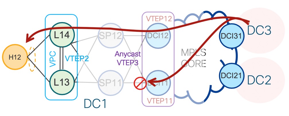
In the direction from DC-2/DC-3 to DC-1, both ASR9k DCI GW nodes receive the same BUM traffic from MPLS WAN. The DF for the tenant VNI forwards traffic to DC-1. Non-DF drops BUM traffic from WAN.
The N9k leaf nodes work in VPC pair and VPC is responsible for prevention of duplication traffic toward VM/Host
3.2. All-Active Multi-Homing VXLAN L2 Gateway
Although anycast VXLAN provides a simple multi-homing solution for gateway, traffic going out of DC may not be properly load balanced on DCI GW nodes. This is due to load balance relying on IGP shortest path metric. A N9k often sends traffic to one DCI gateway only. To overcome the limitation, Ethernet Segment based all-active multi-homing VXLAN L2 gateway is introduced.
Figure below shows the topology of all-active multi-homing VXLAN L2 gateway. In this scenario, all leaf nodes and DCI nodes have a unique VTEP IP. Each N9k leaf node creates EVPN Ethernet Segment (ES1) for a dual-homed Host/Server. ASR9k border leaf nodes create an Ethernet Segment (ES3) for VXLAN facing NVE interface. Traffic from DCI GWs is load balanced between ToRs nodes. The same happens in opposite direction.
Each Leaf sends BUM traffic to both ASR9k nodes. To prevent traffic duplication, only one of the ASR9k nodes can accept VXLAN traffic from N9k leaf. This is done by DF rule. DF election is done at per tenant VNI level. Half of the VNIs elect top DCI GW as DF. The other half elect bottom DCI GW. DF accepts traffic both from DC and WAN. Non-DF drops traffic from DC and WAN. Load balance across VNI is thus achieved on the two DCI L2 gateway nodes.
In all-active multi-homing topology, the data plane must perform ingress DF at VXLAN fabric facing. For the ASM-based underlay option, it’s not a problem, non-DF recognizes multicast encapsulated packets and drop them. But if Ingress Replication is used, DCI GW should have additional identifications to recognize unknown unicast traffic. It hence requires a data plane to implement Section 8.3.3 of RFC 8365 – BUM flag in the VXLAN header. The flag is used to identify L2 flood traffic received from VXLAN, thus a non-DF node can perform ingress drop operation to prevent duplicated traffic sent to a destination.
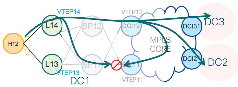
Traffic flow on all-active multi-homing VXLAN L2 gateway is illustrated in figure below. DC1 outbound BUM traffic arrives on a leaf first. Leaf replicates the traffic to two ASR9k DCI nodes. DF DCI nodes flood traffic to WAN. Non-DF node drops traffic from DC fabric. Traffic flooded to WAN goes to DC-2 and DC-3. One copy comes back to DC-1 via bottom DCI node. The bottom DCI node compares the split horizon label in the received MPLS packet. Drops the packet with split horizon rule.
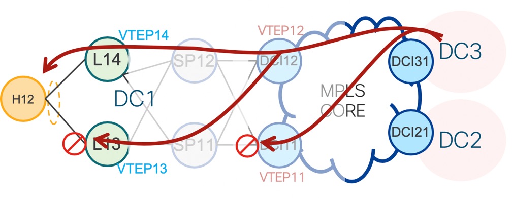
In the reverse direction (picture below), DC-1 inbound traffic from DC-2/DC-3 arrives on both top and bottom DCI nodes. The bottom one drops traffic with DF rule. The top node forwards 2 copies to remote leaf nodes. The N9k leaf nodes apply DF rule before forwarding traffic to Host.
Sources:
Jiri Chaloupka’s presentation from Cisco Live “BRKSPG-3965 EVPN Deep Dive”


